This thread has been locked.

If you have a related question, please click the "Ask a related question" button in the top right corner. The newly created question will be automatically linked to this question.

AWR1243: Cascade design

Part Number: AWR1243

Hello,

I was looking at the cascade design shown in the presentation and I was wondering if the antenna placement could be explained a bit more:

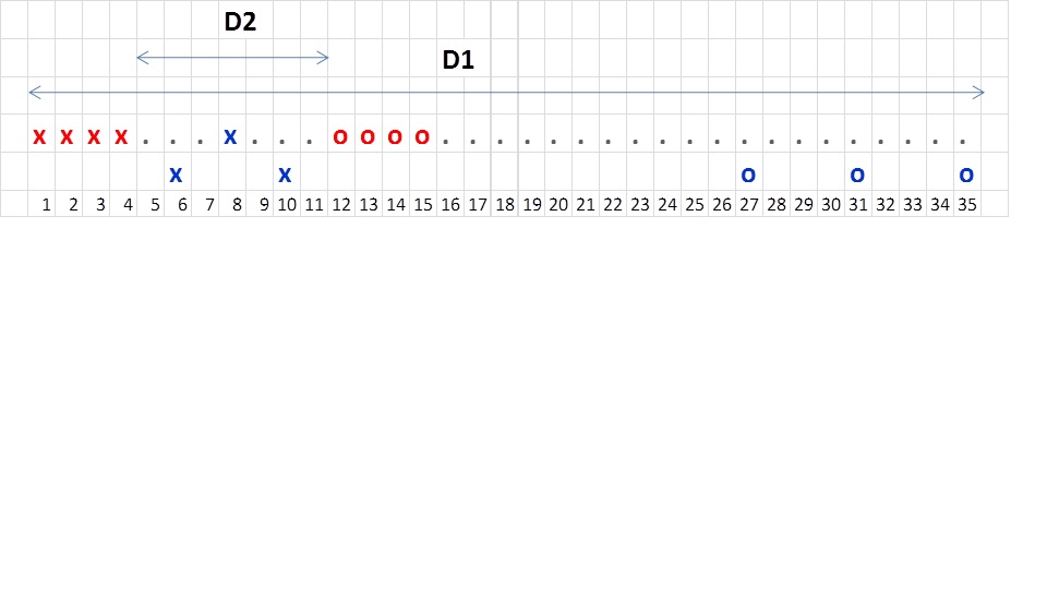
From my basic understanding, if the receive antennas are placed with lambda/2 spacing, the tx antennas are placed at 2xLambda (4 x (lambda/2)). You guys seem to have done that for master and slave seperatly but there is a huge "deadspace" in between the master and slave. So there isn't consistent spacing between the tx antennas or rx antennas.

Wouldn't this result in there being no virtual antennas in that "deadspace"? Would the design that is presented here be the same as if the all the 8 Rx antennas were separated by lambda/2 and each of the 6 TX antennas were separated by 8 x lambda/2 = 4xlambda?

Thank you,

Faiz

  • The picture didn't show up:

  • Hello Faiz,

    In general the virtual antennas generated do not depend on the spacing between the RX and TX antennas. What is important is the spacing between the different RX antennas and the spacing between the TX antennas.

    Below is the antenna configuration used. Blue are the TX antennas and reds are the RX antennas.

    In the above antenna configuration, if you use the 3TX from the master device and all 8 receivers from both the devices you would get the following virtual receiver  array, which is a linear array of 23 virtual receivers. The ones in RED are using receviers of slave device, the ones in BLUE are using receivers of master device. Note that the recevier number (12) below is overlapped with RX4TX1.

    Regards,

    Vivek

  • Hi Vivek,

    Thanks for your explanation. I think I understand that. What I am confused about is when all 5Tx are used with all 8RX.

    There is a big gap between Slave TX2 (position 10 in your figure 1) and Master TX1 (position 27) so there will be a gap with no virtual antennas.

    Another way to express this would be to take the 2 Slave TX and all 8 RX antennas. I believe the array would look something like this (Red is slave rx antennas and blue is master rx antennas):

    <

    STX1RX1 STX1RX2 STX1RX3 ST1RX4 STX2RX1 STX2RX2 STX3RX3 STR4RX4 NO ANTENNAS STX1RX1 STX1RX2 STX1RX3 STX1RX4 STX2RX1 STX2RX2 STX2RX3 STX2RX4

    Yellow is the area with no antennas so there isn't a constant "delay" of lambda/2 for the signals. If this is correct, how is this accounted for?

    I hope that made sense.

    Thanks,

    Faiz

  • Hi,

    The dimension of the section in yellow is also defined in units of lamda/2

    Thank you
    Cesar