This thread has been locked.

If you have a related question, please click the "Ask a related question" button in the top right corner. The newly created question will be automatically linked to this question.

FDC2112: Fdc2112 sensor device advice?

Part Number: FDC2112
Other Parts Discussed in Thread: SN74LVC1G66, LDC2114, FDC2114, LDC1314, FDC2214

Hi All


I would like to know if I could adapt the fdc2112 into our sensing design to replace current capacitance sensing so that we get further accuracy and stability.


We used various substrates such as soil that will be mixed  with water, we would like to determine the preposition of fluid as %. Ideally this would not represent the whole substrate but area or region the PCB electrode.


Would it be possible to use fdc2112 or another device, to determine the capacitance as the preposition of fluid mixed with the substrate increasing?  If so then we can preform various test to determine capacitance against percentage.


The aim is not to measure liquid level, as you would in tank but the preposition mixed.


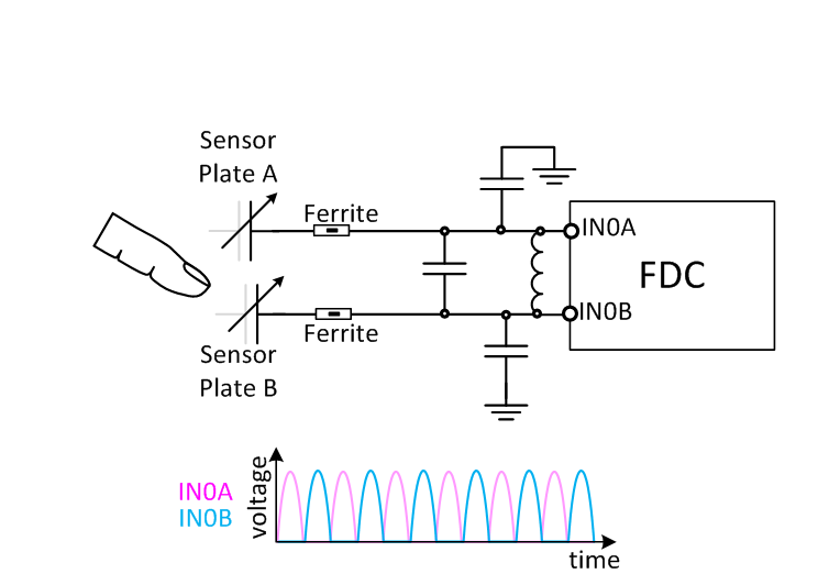
If I am correct using the principles of Fringe capacitance will be required?


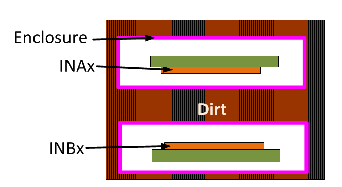
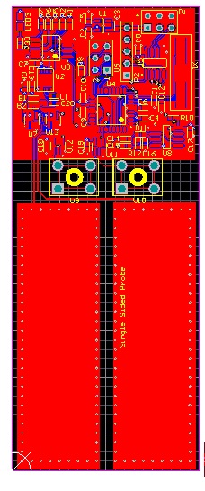
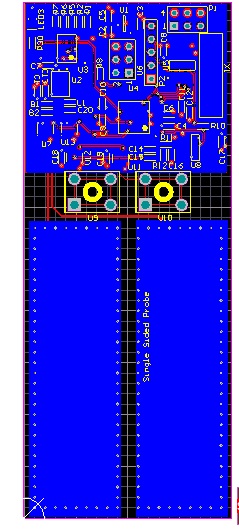
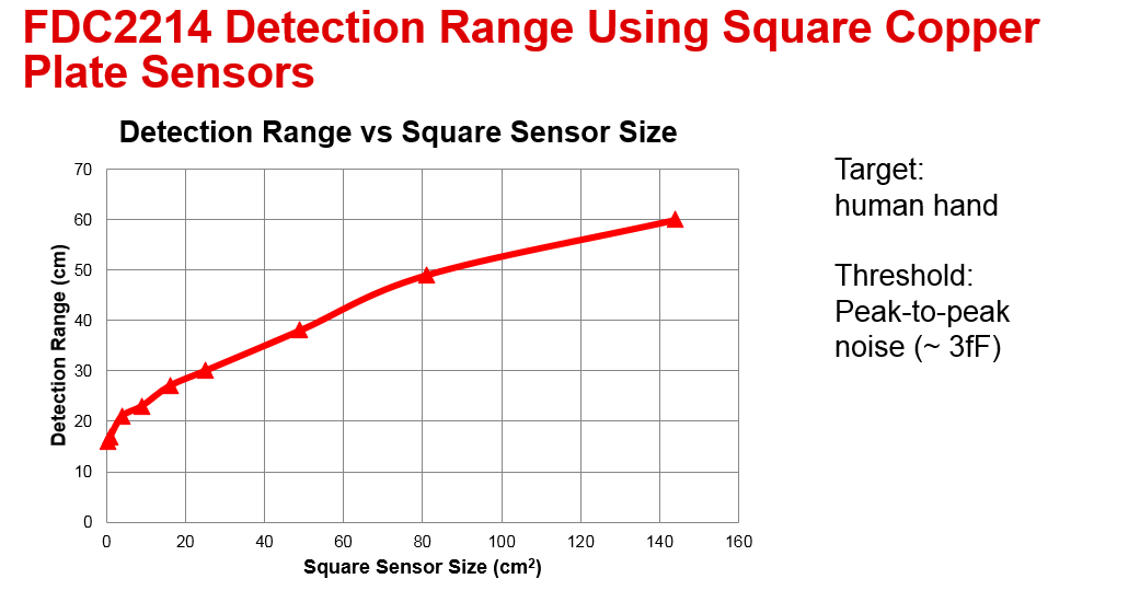
An additional criteria is the capacitance field needs to be beyond 0.5-1cm, so that when PCB is placed in an enclosure it would still be functional and does not require either the substrate or any fluid to have direct contact with the PCB. Would this be possible?


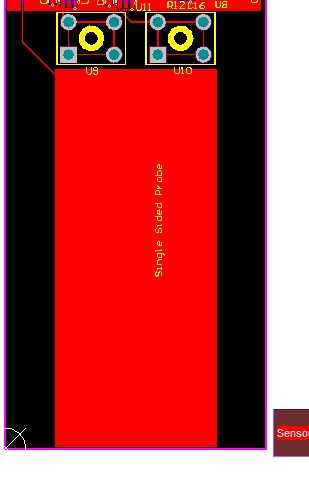
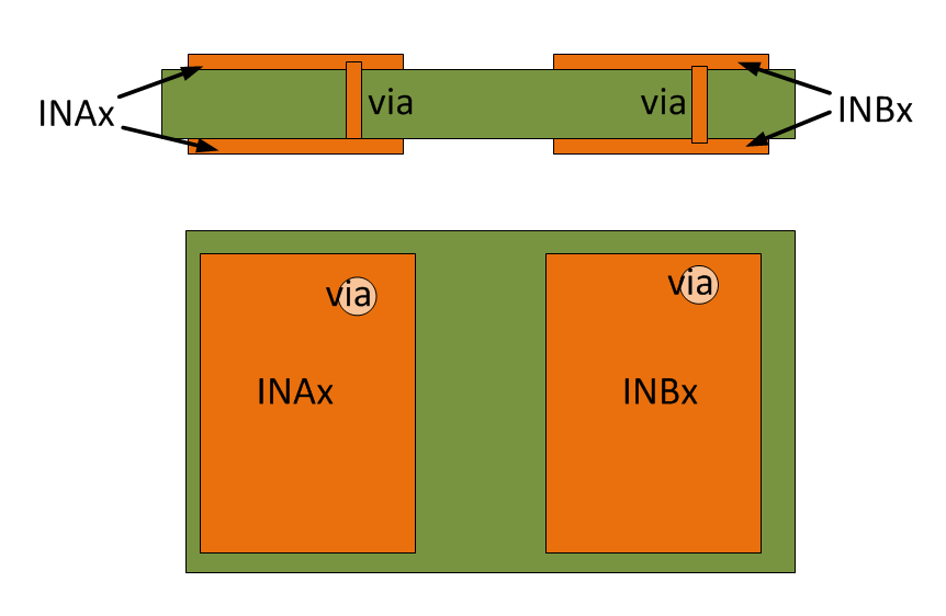
If I am correct the capacitance field in terms of distance is determined by embedded PCB electrode size, but this will also be restricted as it will affect the capacitance, would you be able to advice on the size or pattern?


  • Hello Dharmesh,

    It sounds like you want to measure the amount of moisture in soil, correct?

    While possible, there is some information you will need to find out - primarily, what is the change in dielectric capacitance vs moisture level in soil. This is something I do not have. If the variation in capacitance is not large enough, you may need to have a reference sensor, to compensate for a range of environmental shifts; I don't know the optimum reference sensor configuration for this application.

    Regards,
    ChrisO
  • Dear Chris

    Yes that would be correct.

    Generally the dielectric constant for soil is low while(0-5) water will be about 80, therefore as moisture as fraction increasing with the surroundings the dielectric constant will increase.

    Once this increases so will capacitance, indicating increase in moisture. But this will not directly give us any useful information as we will then need to produce physical samples of substrates as the fraction of water increases and make a graph with moisture fraction against capacitance(readings from the FDC2112) as the reading will not necessarily be linear.

    Please can you elaborate on the reference sensor you mentioned? What we have done in past was to use an analogue switch to isolate the electrode from the sensor so change in environmental temperature can be compensated for with the out need of the user removing the electrode from the substrate or observing the temperature.

    What we need advice on is PCB electrode design so that when connected to the FDC2112:
    1. Capacitance is still in the range of the IC,
    2. Can produce fringe field so that substrate to measure does not need to touch the PCB board, ideally 0.5 -1cm, as pcb will be placed in a casing?
  • Hi Dharmesh,

    The sensor design itself is not very complex - basically, the sensing component is simply a metal plate (often copper or aluminum) of the appropriate size. In general, the physical size of the sensor corresponds to the sensing range, as the electric field size scales with the physical size.

    So for FDC2xxx devices, there is a fixed sensor inductor and capacitor; both are in parallel. The sensor capacitor plate is in parallel with the LC tank. Your proposal of disconnecting the sensor plate from the LDC is fine, as long as the BW of the switch exceeds the sensor frequency.

    Regarding the capacitance range of the FDC211x device - the FDC211x supports an extremely large sensor capacitance range in excess of 10nF. The ratio of the fixed sensor capacitance should not be too large compared to range of sensor capacitance shift; if the sensor capacitance shifts by 10fF and you have 10nF of fixed capacitance, then you will not have enough resolution with the FDC211x to detect the shift; you will need to use the FDC221x. So, a simple rule of thumb on your sensor - make it as big as possible .

    The electric field generated by the sensor will extend farther with a larger sensor. Your sensor also does not need to be on the PCB - it can be a metal area on the case of your system.

    Regards,

    ChrisO
  • Hi Chris

    Is there away to calculate or simulate the sensing range depending on the size of copper area?

    Yes i have noticed that there is a parallel inductor and capacitor , i am anticipating this is there to simply set the minimum capacitance. The sensor plate will be kept in parallel, should there also be a GND below it or a gnd copper pour on the same layer but at certain distance away, maybe 10mm away. I am thinking about using a copper plate size of 25mm x 58mm . If i am correct the gnd for the plate will be know as a virtual gnd?

    The switches that are going to be using is the analogue switches such as SN74LVC1G66. Is it possible for FDC device to output beyond 10Mhz? As the frequency can also have an effect on the measurement. 

    As mentioned that capacitance range for the device is large, we just need to insure the plate prior to any fluid does not exhaust that range so that sensor detection is limited. So i will make the sensor plate as large as possible, but the fixed capacitance should that be set to 10nF or can this be change for optimization?

    Example of what was done previously with another sensor type

    As it was mentioned that sensor plate should be large as possible so ratio to fixed capacitance increase and field range also , would it be better to keep the sensor plate on both layers with multiple via, therefore increasing the area?


  • Hello Dharmesh,

    You are correct about the second "electrode" for the sensor capacitor being a virtual ground. You should make sure that the PCB with the device has ground flood to improve the virtual ground coupling. Having an electrical ground plate behind the sensor can help shield the sensor. Having a larger distance between the sensor plate and the ground helps with the sensitivity of the sensor, as there is a smaller amount of fixed ground.

    For the switch, the SN74VLC1G66 looks ok, but I would recommend checking its performance. You should be able to chain together EVM to see. One parameter to consider is the switch's parasitic capacitance - as the parasitic capacitance is not as stable and could affect your system's performance.

    The FDC211x/221x are specified to a maximum sensor frequency of 10MHz. The devices all have margin on that specification, and so operation can exceed 10MHz, however, the short answer is don't do it for production devices.

    We do have the LDC2114, which can measure capacitance with sensor frequencies up to 30MHz, but it only measures dynamic shifts, not absolute capacitance.

    Commonly, a single layer for the sensor suffices. The second layer sensor pad would only be helpful if it is can also face the dielectric.

    Regards,

    ChrisO
  • Hi Chris 

    Sorry there is a little confusion, the virtual ground I was referring to was the GND pour, which would in theory would become virtual ground for the probe but actual ground of the remaining circuit , you can see this pour starting above component U9 and U10 in the picture. 

    The second electrode I referred to was adding an additional copper plate on the bottom layer and connecting it to the top layer using vias, therefore increasing the surface area. The sensor plate on the picture is referred to as “Single Sided Probe”. Both will be facing the dielectric, as sensor will be fully embedded in the substrate, previously we used only one side and expected it capacitance fields to penetrate through the pcb, but if we can use both sides to have greater range then that would be preferred. 

    The aim is keep a larger distance between plate and gnd so sensitivity of the sensor increases. The reason why sensing range is needed is a)plastic casing b)air gaps in the measure substrates. 

    We can make a prototype PCB with the SN74VLC1G66, but as you mentioned to check performance what else should we be looking into? Or what else should we be looking into? How do we insure parasitic capacitance is not going to be a problem. 

    The only thing that comes into mind if the capacitance the switch introduces to sensor IC, could cause it go beyond its limits. 

    In order to achieve 10MHz, would internal oscillator be adequate? 

    LDC2114, is also an option, as ultimately we want to measure moisture percentage, so even we compare frequency shift to moisture percentage instead of capacitance is work able.

  • Hello Dharmesh,

    Consider using 2 matching sensor elements, where one side is connected to INAx and the other is connected to INBx. This will provide improved performance. Also consider placing a ferrite between the sensor element and the fixed inductor.

    An even better configuration, if you can construct it, would be:

    The sensor frequency is controlled by the sensor inductance and capacitance, not the reference frequency. An external oscillator will have lower noise.

    The FDC supports an extremely large capacitance range (>10nF); just be aware that a very large fixed sensor will attenuate the measured sensor variation due to resolution limitations of the FDC211x. You can always use the FDC221x for such situations.

    Regards,

    ChrisO

  • Dear Chris


    The area on the PCB where the sensor plate can be placed is restricted to size of 6cm by 4 cm, due to possible casing limits.


    I am in process of making a 2L PCB


    If I am correct this area will be split in half , with two sensor plates connected to individual sensor channels. I have not read the datasheet in extreme details, but would this mean I will be getting two sets of sensor readings, channel A and Channel B? Or does the sensor IC do some form of calibration between the two sensor readings and outputs 1 capacitance value?


    As mentioned to place a ferret between plates and fixed inductor if possible can you send a diagram to avoid an error in pcb design, or I can send you my schematic next week just confirm I have done what you have recommended correctly.


    What form of performance will be noticed, as it seems there are two plates compared to one large plate?


    Your diagram shows one via, I was planning to place multiple via, will this cause any issue such as capacitance increase?


    The second suggestion seems good but we are limited to our enclosure. It seems that it two sets of sensor with the substrate kept between them. Maybe once we get some time, we could mod this pcb we designing to perform in that setup.


    As you mentioned

    The FDC supports an extremely large capacitance range (>10nF); just be aware that a very large fixed sensor will attenuate the measured sensor variation due to resolution limitations of the FDC211x. You can always use the FDC221x for such situations.

    From my understanding the fixed sensor, is the inductor and capacitance at the Ic pins.  The aim is to set this to 10mhz and keep capacitance low as possible so I get the full spectrum of measureable capacitance.


    Is there any only tools for simulation and configuration this device as you have for the power supplies?

  • Hi Dharmesh,

    Using the sensor configuration that I provide does not require any specific post-processing on FDC output data. In the configuration, you tie (if using channel 0), one half of the active sensor area to IN0A, and the other half to IN0B. The FDC actually drives the sensor as a half-rectified sine-wave; one channel is always tied to ground. In this way, INxA is your sensor and INxB is its ground; when the phase inverts, then INxB is the sensor and INxA is the ground. The datasheet provides information on this configuration (as a differential sensor configuration) in section 10.1.1); you can view this as a balanced sensor design. This configuration uses only one channel and so the output code is based on the response of both sensor plates.

    Set the center capacitor to the nominal sensor capacitance. You may find that placing INa/b caps to ground improves the performance; the nominal value for those caps should be ~1/2 of the nominal sensor capacitance.

    We do have a cap sensing calculator tool at . We are working on an update to this tool. 

    Regards,

    ChrisO

  • Hi Chris

    Thanks

    According to the datasheet it says

    "

    The single-ended configuration allows higher sensing range than the differential configuration for a given total

    sensor plate area. In applications in which high sensitivity at close proximity is desired, the differential

    configuration performs better than the single-ended configuration

    "

    As i want to read at certain distance away e.g 0.5-1cm away, would single ended configuration be better as it would give me a greater sensing range? Or have i miss understood this point?

    For your reference this is my circuit.

    The inductor and capacitors have been selected to achieve 10Mhz, i believe these values can be changed subject to passive component availability. 

    This is the PCB layout, as you can see at the moment there is two plates, with little spacing between them.  With the GND placed near the component area.

    Would this be correct way to do this PCB , so that sensing range can increase its range?

    Bottom layer

    Thanks

  • Hi Dharmesh,

    That looks good. I couldn't review all of your layout because of graphics compression artifacts in your image file.

    I recommend targeting a sensor frequency below 10MHz, to ensure that you are always below the 10MHz maximum sensor frequency spec even with part-to-part tolerances.

    Regards,

    ChrisO
  • I can send the gerber via email if you prefer. But will this configuration have any effect on sensing range as suggested by the datasheet?
  • Hi Dharmesh,

    The sensor configuration is clear from your posted images; I do not think gerbers are necessary. There will be a small decrease in the sensing range, but this sensor config should have better noise performance that will make up for it.

    Regards,

    ChrisO
  • Hi Chris

    Thanks, i will place an order for some samples and also have the PCB made, and then will report back on the results.. Sorry for the questions, but go the last few questions before i submit my design.

    1. Is there away to calculate the sensors sensitivity to range with the size of the plates,.

    2. As suggested i will change the the values of the capacitor and inductor so it slightly less then 10 MHz.

    3. The sensor plates, analogue switches and tracks will will add additional capacitance. If i am correct this will effect the sensor frequency as were never included in the excel calculator you had sent. Once my sensor is working , would it be a good idea to make small changes to the value of the inductor and capacitor as a compensation factor so 10Mhz can be still achieved, prior to submerged with any fluid or substrates?

    Regards
  • Hello Dharmesh,

    Most of the measurements we have done for scaling sensor size are based on human interaction vs distance; I am sorry but I don't have an easy mapping for your application. We generally evaluate an application using copper sensor plates connected to our EVM before finalizing a PCB.

    As for adjusting the sensor fixed L &C to optimize the oscillation frequency - this is the recommended process.

    Regards,

    ChrisO
  • Hi Chris

    Thank You for your email

    That is understandable , but in principle i am thinking it would be the same.

    For my application i would anticipate the interaction with fluid should produce wide capacitance reading , which will depending on the qty of fluid. Where else with human interaction it would be more of a logical operation that if capacitance is within range X, then acknowledged it as a pressed button. For my application there will be no logic at sensing level as you would for button press style switch. 

    Would you have any information that would show  the relationship between sensing range against ,overlay thickness and plate size ?

    I do not expect it will give me an identical results but i am sure the principles can be applied for my application as well. 

  •  Hi Dharmesh,

    Here is a plot of proximity sensing range vs sensor size.

    Regards,

    ChrisO

  • Hi Chris

    I have made a sample PCB.

    Instead of using a ferrite beads , i have currently used a 0.2ohm resistor . But have ordered some beads so i will replace it.

    At the moment i am using a 10uH inductor and 24pF capacitor. The measured frequency on the electrodes are 6.3Mhz.  So should i change the value of the capacitor so that i can achieve slightly below 10Mhz? 

    I am getting a 12-bit reading , but how much capacitance does each bit represent?

    I was expecting that if i was to hover my hand over the electrodes it would detect some capacitance and i was to get closer this would increase proportionally. But this has not exactly happened, unless i am actually touching the electrodes.  Am i miss understanding any elements , or need to set some register to increase the range?  Is it necessary that there has to be a direct contact with the substance via the overlay?

  • Hi Dharmesh,

    The FDC2114 is lower resolution, with only 12 bits. Investigate using the GAIN setting for the FDC2114 for greater sensitivity. You can refer to section 3.3 of the LDC131x application note for details (www.ti.com/.../snoa945.pdf), as the FDC2114 and LDC1314 work in the same manner.

    If enabling the GAIN up to 16 bits of signal doesn't give you the sensitivity that you need, then you can look into the using the FDC2214 device.
    As for the 6.3MHz operation, that should be fine - you are under the 10MHz maximum sensor frequency spec.

    Regards,

    ChrisO