This thread has been locked.

If you have a related question, please click the "Ask a related question" button in the top right corner. The newly created question will be automatically linked to this question.

TDC1000-TDC7200EVM: Amplitude of pulses

Part Number: TDC1000-TDC7200EVM

Hello,

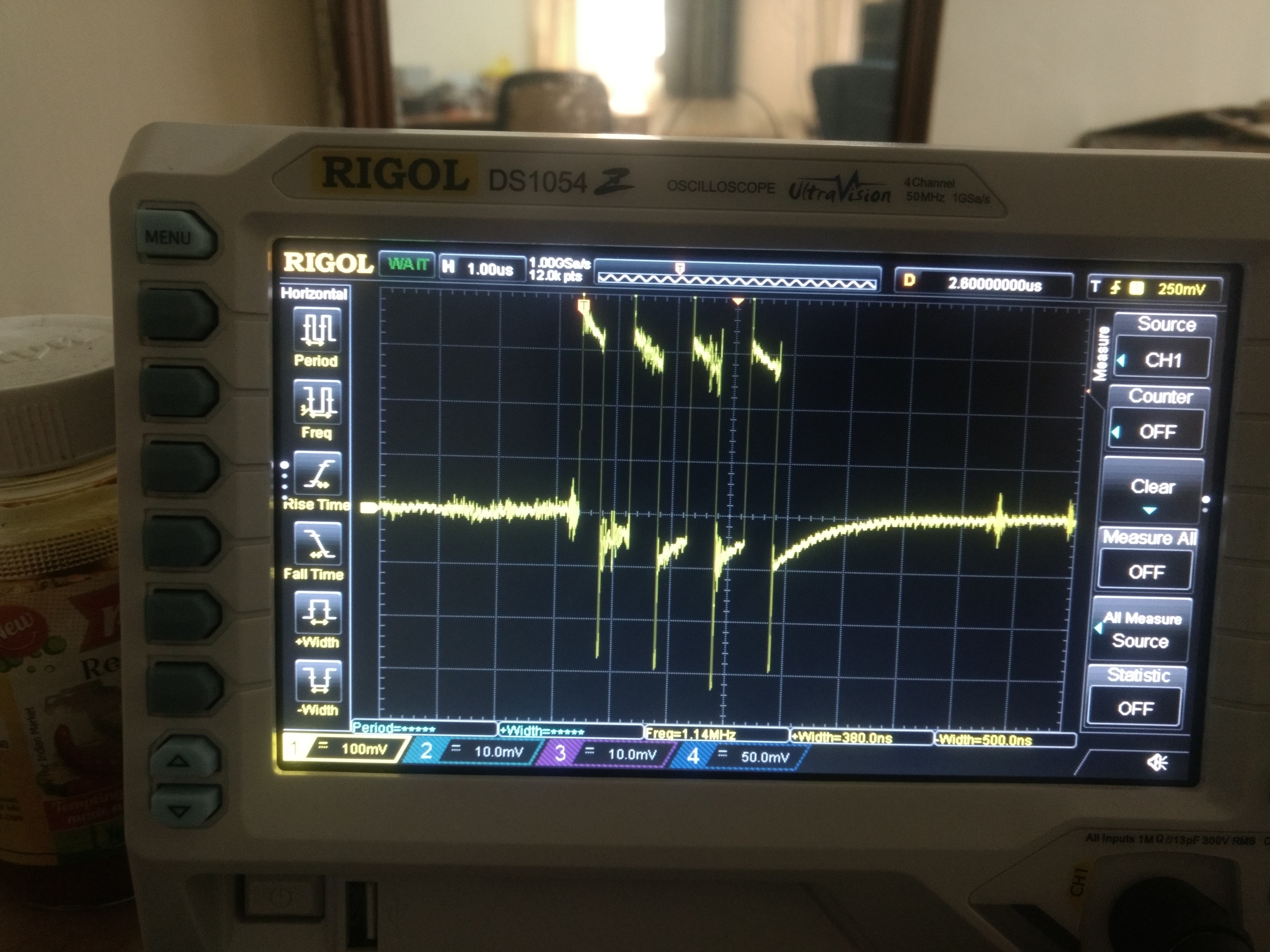
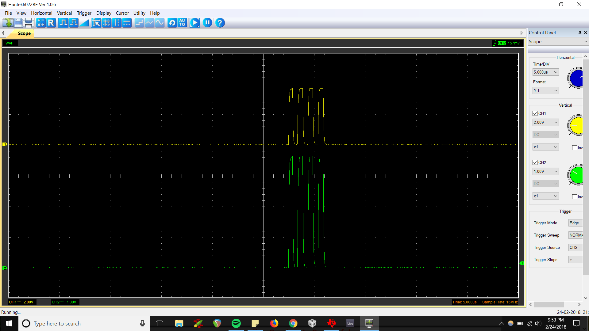
I have checked the signal of transmitting pulses (for flow measurement) in an oscilloscope to be 250mV. Can we increase the value?

Regards,

Prudhvi Sagar.

  • Hello Prudhvi,

    Is there a transducer connected, and how is the transducer connected? The TX pulses should swing from VDD-0.3V down to 0.3V with nothing connected. Depending on the transducer there may be a slight impedance mismatch which causes a loss of voltage.

    For a reference on how to achieve much higher output voltages, see the BSTEVM which is part of the TDC1000-GASEVM. The full schematic is available in the user's guide here: www.ti.com/.../sniu026a.pdf

    Regards,
  • Hello,

    I have connected the oscilloscope directly to the TX/RX channel of the EVM. I was getting nearly 0 - 300 mV pulses. Can you explain more about the impedance matching of the transducers with the line, so that I can be cautious about selecting transducers next time.

    Regards,

    Prudhvi Sagar

  • Hello,

    Were you talking about the values shown in datasheet. This means I am getting lowest possible in the oscilloscope.

    If I tune the impedance of oscilloscope would I get a better output. This means the transducers to be selected should be impedance matched to 75 ohms?

    Regards,

    Prudhvi Sagar

  • Hello,

    Is it advisable to make a board using the given reference design files for EVM and keep slots to solder resistors and capacitors to match impedance with all transducers I want to test with.?

    Regards,

    Prudhvi Sagar

  • Hello,
    Kindly help me understand impedance matching with transducers in a better fashion.

    Regards,
    Prudhvi Sagar
  • Hi Prudhvi,

    When you are testing the scope probe on the TX pin, what are the settings of the probe? Is it high impedance or 50ohm?

    Also, you are testing the TX2 pin in this configuration. Have you set the GUI to output on CH2? What does it look like when you move the probe to TX1?

    Regards,
  •  Hello Scott,

    Thank you for the support. I have changed the oscilloscope and now probed as you have described. Now I am getting near 3.3V as you have suggested. I have checked with probes of my oscilloscope. They are high impedance probes in the order of M Ohms. I checked with my previous oscilloscope. It has a 50 Ohms probes.

    So I think maintaining a high impedance in the trace will be a best output to deliver TX signals to the transducers. Do you think my way of analysis is correct?

    Regards,

    Prudhvi Sagar.

  • Hello Scott,
    Can you give me an order in which the impedance of transducer to be at the resonant frequency for good performance. I would like to check this parameter while purchasing further transducers.

    Can I tweak anything at the circuit design level compared to the EVM design to improve the results?

    Regards,
    Prudhvi Sagar.
  • Hi Prudhvi,

    I deleted my other post because it had some misleading information. The scope probe impedance must be high so that it does not act as a load and influence the measurement.

    The transducer itself is at its lowest impedance and highest admittance when it is at its resonant frequency. See here: www.piezotechnologies.com/.../overview-piezo-materials

    No further circuit changes should be necessary to get decent results with most transducers.

    Regards,