This thread has been locked.

If you have a related question, please click the "Ask a related question" button in the top right corner. The newly created question will be automatically linked to this question.

LDC1312: Inductive Sensing for stainless steel

Part Number: LDC1312
Other Parts Discussed in Thread: LDC1612

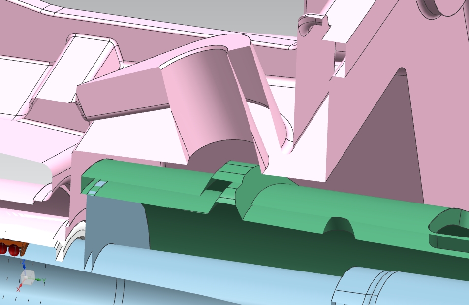
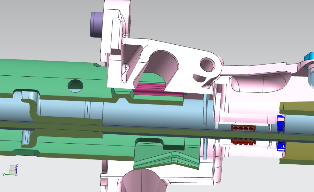
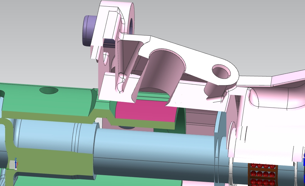
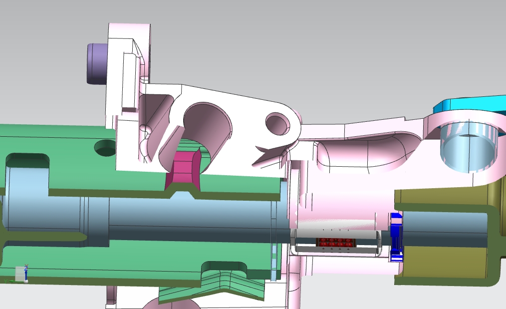
I need to sense the stainless steel target in my project, which i am doing with LDC1312. The target is is gear position sensing 

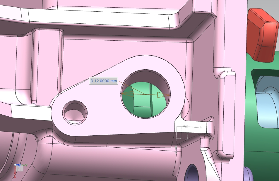
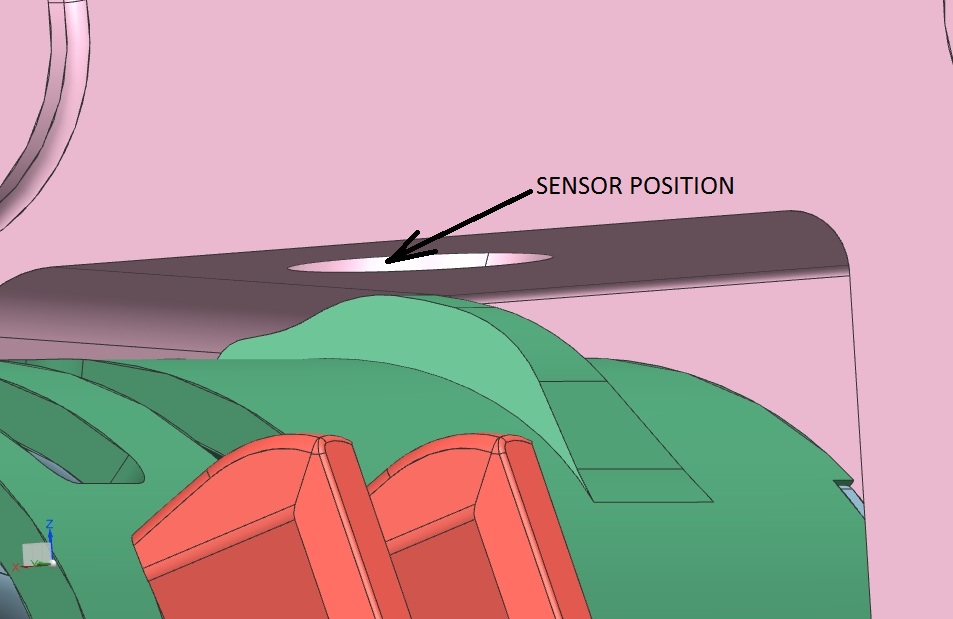
which has three gears and i need to sense three positions. There is a 12mm hole through which i need to sense the movement on

the other side as the gear moves the amount of metal in front of the hole changes which will reduce the distance between target and

the hole. I am attaching the images for reference. The whole material is of stainless steel so i want to avoid the interference caused by

material in pink and want to sense only the green colored material.

Please tell me what configuration is necessary to calculate the count in register 0x00. Also i need a difference in count when the steel

is more and when it is less.

Regards 

Sarang


  • Hello Sarang,

    This application looks reasonable, but there are a few details needed. I assume you plan to place the sensor into the viewing port.
    1) How far will the gear be from the sensor?
    2) How high are the gear bumps?
    3) How quickly do you need to sample?
    4) Do you need to only monitor while the shaft is rotating or do you need to know when the teeth are aligned with the sensor?

    It looks like a 10.5mm diameter active area sensor (this gives you edge clearance on the sensor so that the sensor PCB can fit into the tube) with 330pF sensor cap should work quite well. Using 0.125mm trace/space rules will allow 19 turns, and with a 2layer, 1mm thick PCB you should have a pretty good sensor for this application.

    Regards,

    ChrisO
  • Hello Chris

    The shift in gear will move the green portion which acts as a shaft to the gear so there are

    three gears the movement will be approx 45 degrees(for first to third gear). For the queries:

    1. The sensor will be fitted in the pink hole at the end sensing only the shaft(in green).

    2. The bumps are approx 6.5 to 7millimeter.

    3. The sampling should be done as the gear changes so as far as i am concerned with the 

        timing it will require in between 1 to 15 msec(or should be updated as gear position changes).

    4. I only need to sense the shaft positions.

    As for the sensor mentioned by you i don't have any tooling for making such PCB's so if you could suggest

    something it would be better. 

    Thanks,

    Sarang

  • Hi Sarang,

    Please clarify when you say that the sensor will be at the end of the whole. Will the sensor be at the end closest to the shaft? What is the expected distance from the sensor to the shaft? How high do the gear teeth protrude above the shaft?

    As for getting a sensor, we have a sensor EVM which does have a 10mm diameter sensor. Take a look at www.ti.com/.../ldccoilevm. You can use this sensor with the EVM by detaching the sensor coil that comes on the EVM. There are connector holes on the EVM which you can then use to connect to the desired sensor. I recommend using twisted pair to route to the sensor.

    Regards,

    ChrisO
  • Hello Chris,

    Yes the sensor will be close to the shaft, the distance of shaft from sensor will be 1.5mm for the green shaped dome and 

    the plain surface of shaft is 3.45mm. Also i have discussed with our PCB team few queries are there:

    1. The 19 turns on the coil are per layer or adding up both layers.

    2. how much should be the sensing area on the 10.5 diameter coil.

    3. 0.125mm trace/spacing - how does it fit in 10.5mm diameter? as 0.125*2=0.25

        19/0.25 = 76.

    I have tried the measurements on webench with 19 turns per layer it requires a diameter of 15mm. 

    Thanks,

    Sarang. 

  • Hello Sarang,

    It is 19 turns per layer. The outer diameter of the outermost turn is 10.5mm; this should allow you create a 11.5mm diameter PCB which will fit into a 12mm hole. A 0.125mm trace/space is the same as 5mil.

    The webench sensor designer wants to optimize the sensor to have an inner diameter of 30% of the outer diameter; this produces the highest Q sensor, but for many applications it is not a necessary optimization. I have used the LDC tools spreadsheet to calculate your sensor as:

    Regards,

    ChrisO

  • Hello chris 

    I am also using a housing which reduces the diameter to 10mm max also i have 

    ordered LDC1612 as it is 28 bit IC. I have designed a sensor which is possible to design for our

    PCB team i am attaching the link please check.

    webench.ti.com/.../

    Thanks

    Sarang

  • Hi Sarang,

    That sensor looks good, but I would recommend 15 turns instead of 11 turns, as your target is going to be rather close to the sensor.

    Regards,

    ChrisO
  • Hello Chris,

    I am using LDC1612 for my application now and as a sensor can i use a inductor. I have tested with two inductors of 300uH and

    1722uH. The values i am getting are good for calibration for sensing two positions of plain portion and the elongated curvature in 

    green color, but when i am rotating the shaft by one position and bringing back to original position then the change in reading is not much

    so it is difficult to calibrate between two different angular positions of shaft in front of the drill hole of sensor. Would you suggest me

    some technique for sensing such positions.

    The area/material is somewhat same with only angular shift in shaft which has to be sensed for neutral position and change in gear. 

    Thanks

    Sarang

  • Hi Sarang,

    300uH is a lot of inductance for a 10.5mm diameter sensor; how was it constructed? You may want to refer to the sensor design application note: www.ti.com/.../snoa930.pdf. Also, www.ti.com/.../SNOA957 and www.ti.com/.../SNOA945 will be helpful.

    Regards,

    ChrisO
  • Hello Chris

    The inductors that i have used are leaded inductors so they are not sensors, but can i use them and also guide

    me on sensing two different positions with same area for sensor, but only angular changes on the shaft.

    Thanks

    Sarang

  • Hi Sarang,

    The LDC can use leaded wire-wound inductors, although for many applications a flat spiral wound PCB inductor provides more consistent results.

    Please clarify your question on the positions of the sensor - if you can provide a diagram it will be helpful.

    Regards,

    ChrisO
  • Hello Chris

    I am attaching the reference images for sensor position and what positions are to be sensed, when the shaft moves the respective

    purple colored area will be in front of the inductor. The inductor is place horizontally with respect to the drill hole, so the winding are facing

    the sensing area.

    The different sensing positions are as follows:

    Thanks

    Sarang

  • Hi Sarang,

    While LDC can use either wire wound or PCB inductors, I would recommend a flat spiral PCB sensor if possible. In general, wire wound inductors have larger unit-to-unit variations higher inductance, and lower SRF.

    It looks like a PCB inductor is viable for your design.

    Regards,

    ChrisO
  • Hello Chris

    I have a inductor PCB with 4uH as inductance without target and i have used capacitors of 220pF and 22pF

    but the variation is too much it varies from 8000 to 60000 with random values. Do i need to place the capacitor on the 

    sensor board itself or can i place it on my MCU board.

    Please suggest what capacitance can be used for 4uH inductance without target.

    Thanks

    Sarang

  • Hello Sarang,

    The sensor cap is used to both set the sensor frequency and also stabilize the sensor frequency. Take a look at the Sensor Design App-Note: http://www.ti.com/lit/snoa930 for information on the sensor frequency. Also, refer to the Target Design App-Note: www.ti.com/.../snoa957a.pdf, for guidance on what to set the sensor frequency.

    Regards,
    ChrisO
  • Hello Chris

    I have made some changes in the settings of LDC1612 by adjusting CH0_Input_freq and internal clock frequency divider

    but the problem is, i have checked in a sample board which provides some range for all three positions and another board

    which is to be used gives variations in count and is not stable, both the boards have same configurations and same code

    is used but both give different outputs, is there any design constraint that is going wrong which causes variation in count,

    I am not having any component on board other than LDC and MCU.

    Thanks

    Sarang

  • Hi Sarang,

    Can you check the sensor signals with an oscilloscope? You want to make sure that you are providing enough time for the sensor signal to settle, that the sensor frequency is as expected and does not have any transients, and that the amplitude is within the recommended range of 1.2V - 1.8V pk.

    Probe INxA and INxB referenced to ground; the signal should be a half-rectified sinewave. I also recommend using a 1k isolation resistor between the sensor and the probe - this is useful to reduce the parasitic loading from the probe itself.

    Regards,

    ChrisO
  • Hello Chris

    I have checked the sensor waveform but i am getting square waveform, I have used another board which is having some count range for three positions

    but it is not stable i have used the same inductor of 1800uH and capacitor of 100pF.

    The various parameters are as follows:

    Fsensor0=Fin0= 0.3751MHz (formula : 1/(2*pi*sqrt(L*C)))

    Fref0 = 43MHz/2 = 21MHz(approx 20MHz internal oscillator)

    conversion time Tc0 = 0.9msec

    settling time Ts0 = 8usec

    DEGLITCH = 1 MHz

    Do the values match the required specifications for LDC1612, or do i need to change them.

    Also could you tell me how can i add shielding to my inductor as fringing effect can be generated

    in other fields which have not to be sensed. I have tried providing ground but it resulted in variations

    in count.

    thanks,

    Sarang

  • Hello Sarang,

    What is distance between the sensor and the LDC? Also, what is your sensor signal amplitude? The sensor signal should not be a square wave.

    Regards,

    ChrisO