Other Parts Discussed in Thread: , UNIFLASH
Hi,
I am designing a test board base on AWR1243 and FPGA,i found not enough detail in datasheet,
Q1.AWR1243 datasheet of version SWRS188 –MAY 2017 have no details about Power up suquence,any Power design recommendation?
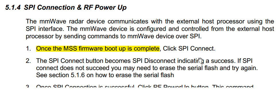
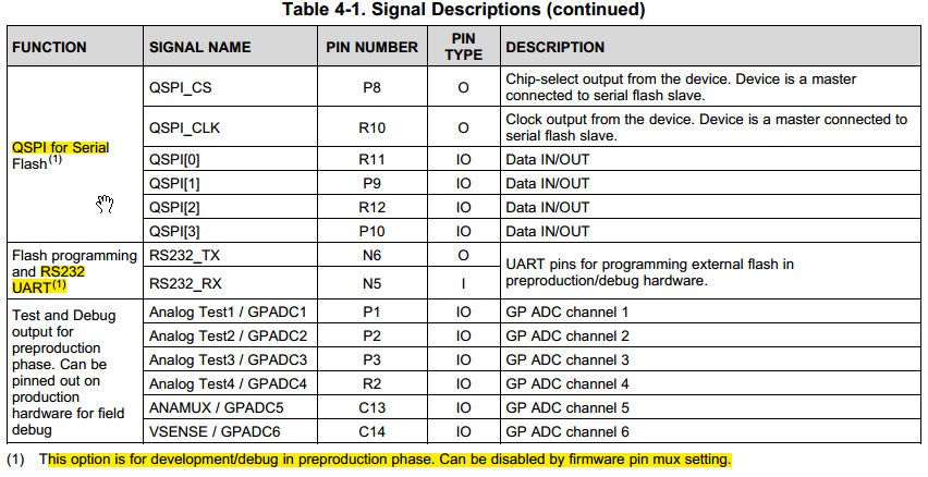
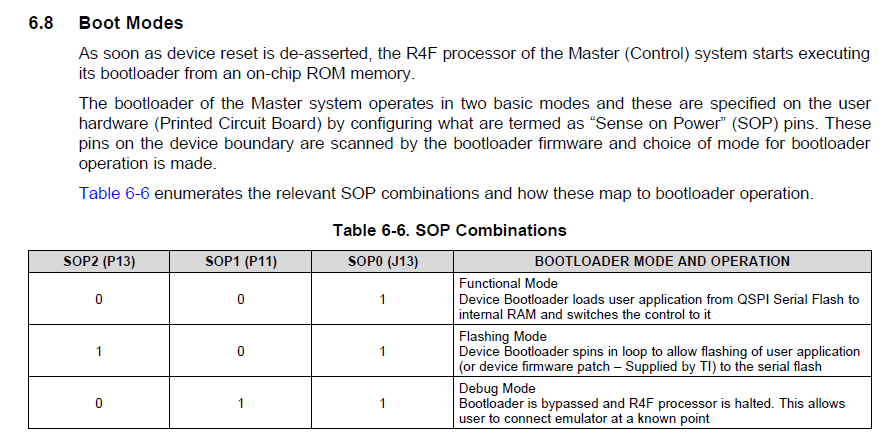
Q2.AWR1243 control port is SPI,which is connected to FPGA in my design,what is the SPI start up sequence?How to control tranceivers,any document and register map description? is it possible to run AWR1243 without any software assistant(No Soc in my current design)?
Q3.the data interface is CSI2 or it can be configured to normal LVDS?