This thread has been locked.

If you have a related question, please click the "Ask a related question" button in the top right corner. The newly created question will be automatically linked to this question.

IWR1443BOOST: TX FMCW output wave form and frequency bandwidth with Visualizer

Part Number: IWR1443BOOST
Other Parts Discussed in Thread: IWR1443

Hi Experts,
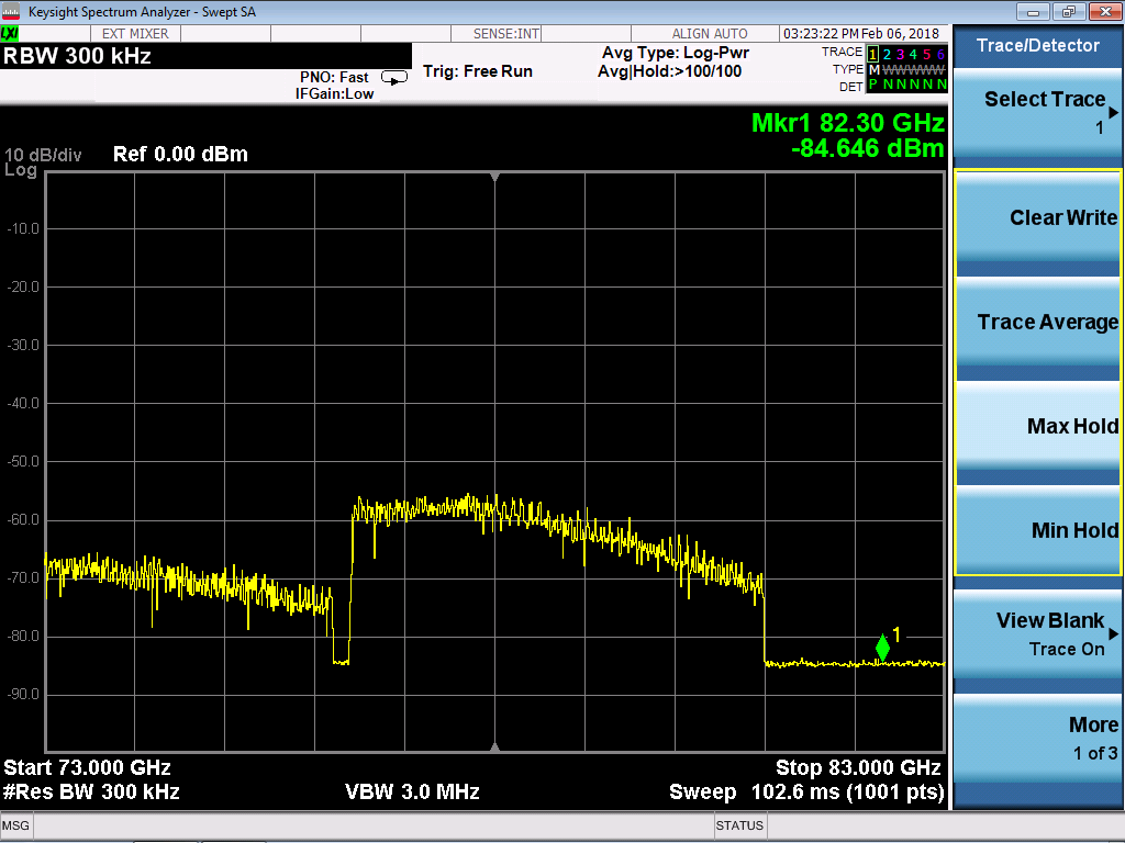
Our customer measured the TX FMCW output with a spectrum analyzer N9010A by Keysight and N1970W Harmonics Mixer by Keysight.
System: IWR1443BOOST ES2.0 with mmWave Demo Visualizer.

1) As you can see, somehow TX signal appears below 76MHz
  The capture data is attached.
  Could you please let us know the possible reason and what we should check customer’s measurement environment?

2) The output TX FMCW frequency was selected from 77 to 81GHz by Visualizer.
  However, the TX output start frequency is from approx. 76.5GHz.
  This might be a problem.
  Could you please check whether it is correct?
  Also, if there is any configuration needed, please let me know.

Best regards,
Hitoshi


  • Hello Hitoshi,

    This is very interesting and definitely not the expected behavior. I've asked one of our experts to look at this and someone should have an answer for you in next few days.


    Cheers,
    Akash
  • Hello Hitoshi,

    If you are performing critical RF measurements, you might substitute a 40Mhz reference clock for the crystal, and to lock the measurement equipment 10Mhz reference. The spectrum analyzer should be locked to the harmonic mixer at 10Mhz (REF OUT of Spectrum Analyzer to REF IN of Harmonic Mixer, REF OUT of Harmonic Mixer to a Synthesizer REF IN). The Synthesizer would be set to provide a 40Mhz sine output, through an AC coupling cap to the EVM with a 1v output.

    On the EVM you would need to perform the following modifications, remove Y1, replace C9 with 50 ohm resistor. replace C15 with a 50 ohm resistor. Connect the 40Mhz AC coupled input to the junction of Y1 and C15.

    Note: the 40Mhz clock needs to be present before the mmWave sensor IWR1443 is taken out of reset.

    To check on the RF accuracy, if you use the continuous output mode, with a single Tx frequency, it is easier to debug the frequency error.

    In the datasheet, the crystal error is specified at 50ppm. So with a continuous frequency of 77Ghz, we would expect 76996150, to 77003850.

    Another possible source of error is the precision of the 19 to 20.25 synthesizer divider. This is usually a small error.

    Regards,

    Joe Quintal
  • Hi Joe,
    Thank you so much for your kind explanation for the points where we should check.
    Will follow your advice and work with the customer.

    We try to understand the reason with the experiment.
    Best regards,
    Hitoshi Sugawara
  • Hello,

    The contribution to the frequency output are:

    continuous single Tx mode

    accuracy of 40Mhz clock

    accuracy of programming the synthesizer start frequency in the RF profile.

    The chirp can have an offset frequency, which is normally zero.

    Let us know if you need more collateral.

    Regards,

    Joe Quintal

  • Hi Joe,
    I am sorry about my belated reply.
    This was successfully resolved by following your advice.
    This was caused by the local oscillation by the Mixer itself.

    Thank you so much for your kind support.
    Best regards,
    Hitoshi