This thread has been locked.

If you have a related question, please click the "Ask a related question" button in the top right corner. The newly created question will be automatically linked to this question.

AWR1642BOOST: I am using AWR1642BOOST CANFD to transmit classic frame.

Part Number: AWR1642BOOST
Other Parts Discussed in Thread: AWR1642, MMWAVE-SDK, AWR1443

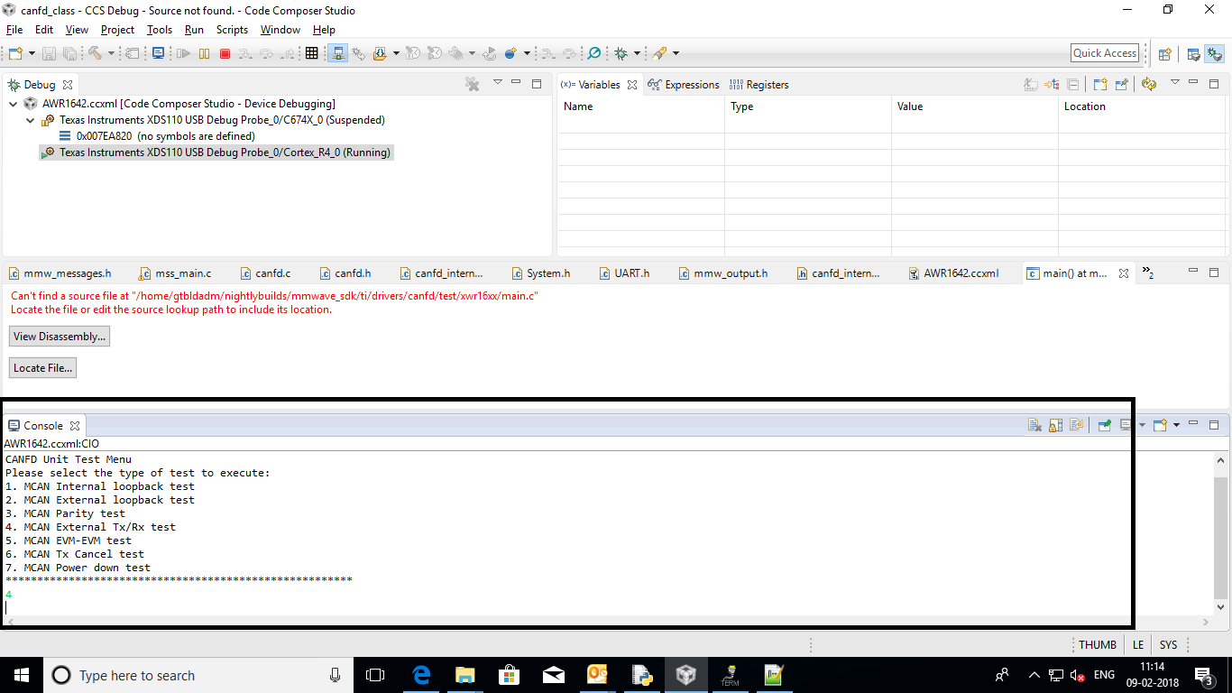
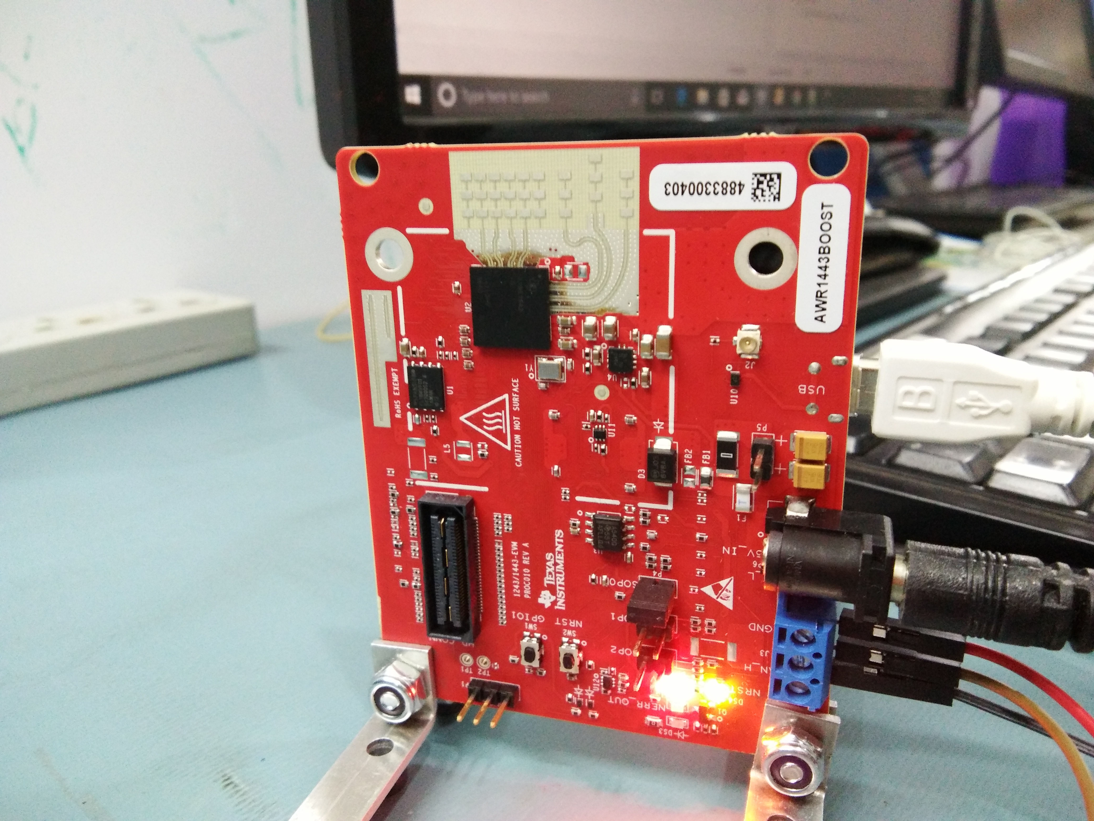
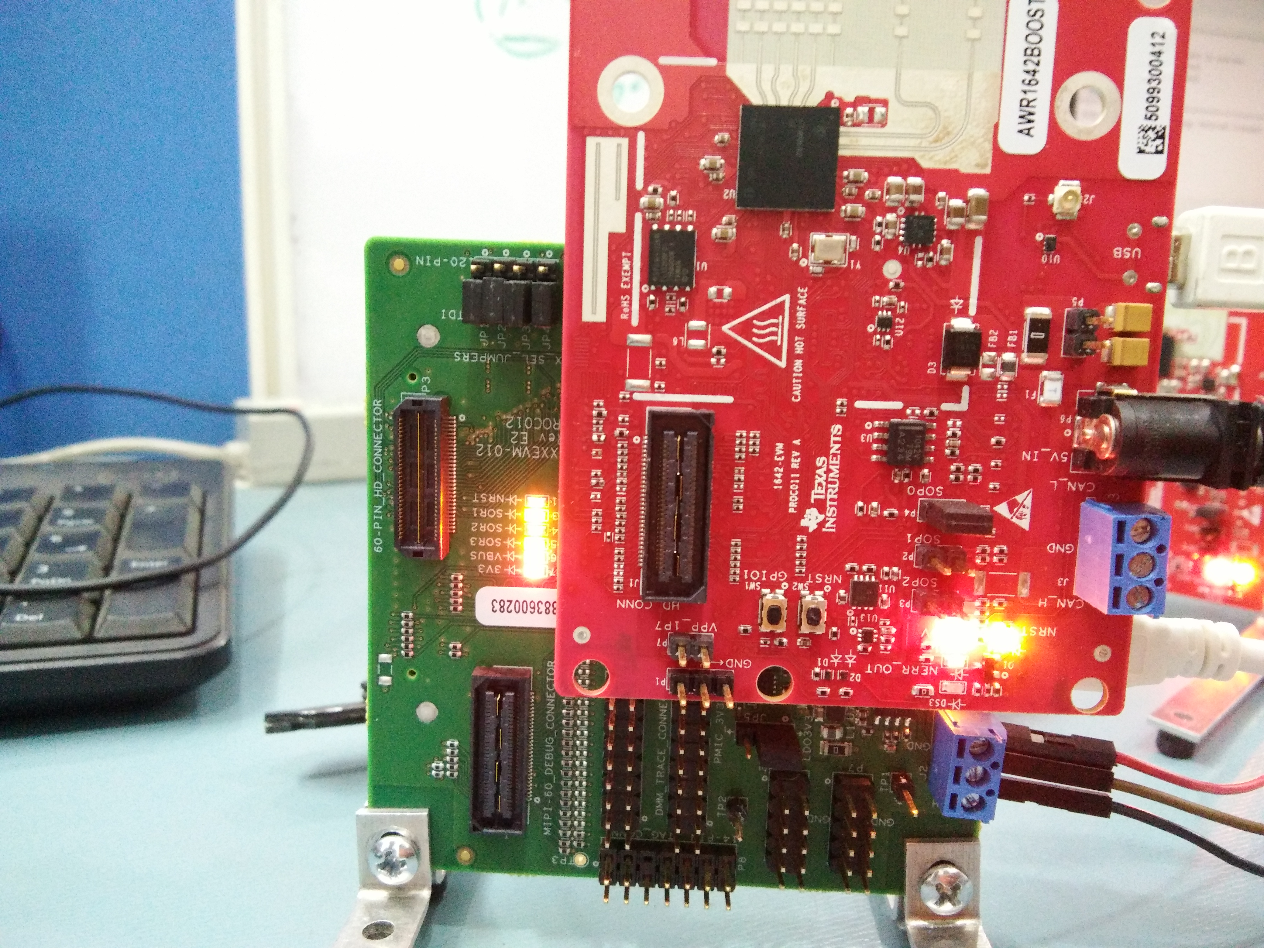
->I am using AWR1642BOOST CANFD to transmit classic frame.I have done necessary ECO changes mentioned in other forums(Removing R6 AND R4,keeping 0 ohm in R11 and R12)and frametype changed to classic.I have taken CANFD code from"C:\ti\mmwave_sdk_01_01_00_02\packages\ti\drivers\CANFD" and integrated to MMW DEMO code (removed internal external looping code) since my intention is to check CAN communication with demo code.I have ensured mcanTransmitTest() is called in this integrated code(verified by writing test byte to uart just before mcanTransmitTest() call).

->on receiver side we connected MCB2300 board from KEIL(since we don't have vector canoe or other tools at the moment).we have following CAN module settings 

#define  PCLK            24000000                /* Peripheral clock, depends on VPBDIV */

/* Values of bit time register for different baudrates

   NT = Nominal bit time = TSEG1 + TSEG2 + 3

   SP = Sample point     = ((1+TSEG1+1)/(1+TSEG1+1+TSEG2+1)) * 100%

                                                                                                   SAM,  SJW, TSEG1, TSEG2, NT,  SP */

const uint32_t CAN_BIT_TIME[] = {         0x0001C000, /* 0+1,  3+1,   1+1,   0+1,      4,         75% */

                                                                          0x0012C000, /* 0+1,  3+1,   2+1,   1+1,  6,        67% */

                                                                           0x0023C000, /* 0+1,  3+1,   3+1,   2+1,  8,     63% */

                                                                       0x0025C000, /* 0+1,  3+1,   5+1,   2+1, 10,      70% */

                                                                     0x0036C000, /* 0+1,  3+1,   6+1,   3+1, 12,      67% */

                                                                    0x0048C000, /* 0+1,  3+1,   8+1,   4+1, 15,      67% */

                                                                      0x0049C000, /* 0+1,  3+1,   9+1,   4+1, 16,   69% */

                                };

 I can choose any one of above configuration and also I don't see two different configuration parameters like nominal and datatime segments in receiver side board 

configuration.

a) so is it necessary has  to be MCAN supported board in receiver side (I don't know MCB2300 board is of which type CAN).

b) If not,what are all the CAN configurations in receiver side has to exactly match with sender side(AWR1642 BOOST - CANFD CLASSIC FRAME)?

ex: peripheral clock,baudrate ..etc

c) I tested by connecting CANH,CANL,GND to MCB2300 board CANH,CANL,GND pins and tried with 

0x0025C000, /* 0+1,  3+1,   5+1(nominaltseg1=5),   2+1(nominaltseg2=2), 10(Networktime),      70%(sample point) */ 

but I am not receiving any CANRX interrupt on receiver side. 


Thanks,

PTKRISHNA.


  • Hi,

    Did you check with a scope that you get the right signals through the Can pins?

    Thank you
    Cesar
  • Hi Cesar,

    I have verified with scope/multimeter.It seems the voltage difference between CANH,GND is always 2.5v even when program is running.It seems the problem

    with integrating CANFD code into demo code. so I want to go back to standalone CANFD debug code provided in "C:\ti\mmwave_sdk_01_01_00_02\packages\ti\drivers\canfd\test\xwr16xx" and test CAN communication alone .but it seems testselection is zero in " canfd\test\xwr16xx\main.c" .I want to change the testselection

    and regenerate "xwr16xx_canfd_mss.xer4f".

    ->could you please point me how to recompile(which make file to be called)Any installations (python ..etc) are needed  to regenerate "xwr16xx_canfd_mss.xer4f" located in path

    "C:\ti\mmwave_sdk_01_01_00_02\packages\ti\drivers\canfd\test\xwr16xx" ?

    ->once this is done I will integrate this into demo code and retest.

    Thanks,

    PTKRISHNA.

  • Hi Cesar,
    In additional debugging after verification with oscilloscope/multimeter,we observed always
    "MCAN_INTR_SRC_TRANS_CANCEL_FINISH" interrupt is always generated (placed uart log in MCANAppCallback function and it shows always "CANFD_Reason_TX_CANCELED" is true always).

    ->Any suggestions in which cases this interrupt is generated as I am just calling mcanTransmitTest() function as mentioned in original question.

    could you please suggest answers for above post query along with this .

    Thanks,
    PTKRISHNA.
  • Hello PTKRISHNA,

    If the receiver side does not support CANFD, you can setup the CANFD on device side to send CLASSIC_CAN frames .

    There are very minimal changes to be done on CANFD application code to send the data in CLASSIC_CAN mode.

    Please refer to the below post for the modification to send data in classic CAN mode.
    e2e.ti.com/.../2316239

    Let me know if you need further information.

    Thanks,
    Raghu
  • HI Raghu,

    I have seen those posts already.following information is needed as I mentioned in previous post already.main.c file in 

    "C:\ti\mmwave_sdk_01_01_00_02\packages\ti\drivers\canfd\test\xwr16xx" testselection variable value is 0 by default.

    I want to change testselection to a valid value in program and regenerate "xwr16xx_canfd_mss.xer4f" file .

    ->I want to know how to recompile ,which make file to recompile (python ..etc needed) to this?

    (or) without recompiling can I give testselection value dynamically?

    please see attached screenshot as well.

  • Hello Krishna,

    Please refer to the user guide in the "MMWAVE-SDK" and refer for section "4.4.3 Building demo" . Please make sure all the dependent tools are installed before building the driver or demo .

    You can then hard-code the testselection =4 , to perform external CAN communication.

    Thanks,
    Raghu

  • Hello Raghu,

    I have changed my test setup to DCAN interface since I have only awr1443 board in receiver side.

    sender side: awr1642 is connected to dev pack and all required ECO changes are done to access CAN2 connector on devpack(DCAN)

    and executing ti\driver\can test code for "awr16xx.xer4f".we have verified CANTX is happening at sender side(waveform on high and low lines in oscilloscope).

    Receiver side: awr1443 board running with "awr14xx.xer4f" .but there is no breakpoint being hit in receiver side DCAN0,DCAN1 ISR.testselection is 0 in receiver side.

    ->Is it correct to place receiver board also in debug mode to test the received data from sender.(or) we have to flash binary in receiver side?

    ->we have placed both boards (SOP 0 JUMPER IS connected ,SOP1,SOP2 are open on both side).Attached setup pictures below.

    Thanks,

    PTKRISHNA.

  • Hi Raghu,
    I am able to solve above problems and see CAN test data on receiver side CAN board.

    Thanks,
    PTKRISHNA.
  • Hi Krishna,

    What was the problem on your side?

    -Raghu
  • Hi Raghu,
    As First step,I have ensured all ECO changes are done on both sides(sender :awr1642 DCAN, Receiver :awr1443).Then Tested with can drv test code for awr16xx provided under ti folder.Able to see voltage changes on CAN pins through oscilloscope.
    On receiver side ,After loading can drv test code provided in ti,I have done additional changes like added new test selection "5" which does all initializations (similar to what dcantrasmittest(),dcanparitytest() ),sets TLV to DCAN mode and waits for check of "grxDoneFlag" to be true.(if it is true I am reading dcanrx array).

    probably this is what it is done in dcanappcallback() already .

    Thanks,
    P Tulasi Krishna.