This thread has been locked.

If you have a related question, please click the "Ask a related question" button in the top right corner. The newly created question will be automatically linked to this question.

AFE4404: TX lines issues on Analog front-end 4404

Part Number: AFE4404

Hi guys,

I have been working on Heart rate 3 click (HR3) which is a development kit having built-in AFE4404 and SFH7050. I successfully got it working by using Arduino Nano. 

The way I did was to configure HR3 based off the table 12 on AFE4404 data sheet and then using attachInterrupt() on Arduino Nano to sense the rising edge of each pulse from ADC_RDY  in order to trigger reading from a corresponding register on AFE. 

Then I started to test on AFE4404  breakout board that I ordered from a manufacturing company with SFH7050. I have a couple of issues with the hardware.

  1. Only one TX1 worked.
  2. ADC_RDY on AFE4404 breakout board did not generate pulsatile signal at 100 Hz. There was literally nothing coming from ADC_RDY.

I have attached all screenshots for signals from TX1, TX2, TX3 on AFE breakout board and the pulsatile signal (100Hz)  from ADC_RDY on HR3 development kit and AFE breakout board, respectively.

 Fig1 : TX1 (blue signal - Green LED) vs TX2 (red signal - Red LED)

Fig 2: TX1 (blue signal - Green LED) vs TX3  (red signal - Infrared LED)

Fig 3: ADC_RDY signal from HR3 (Development kit) - Direct measurement on ADC_RDY pin on HR3.

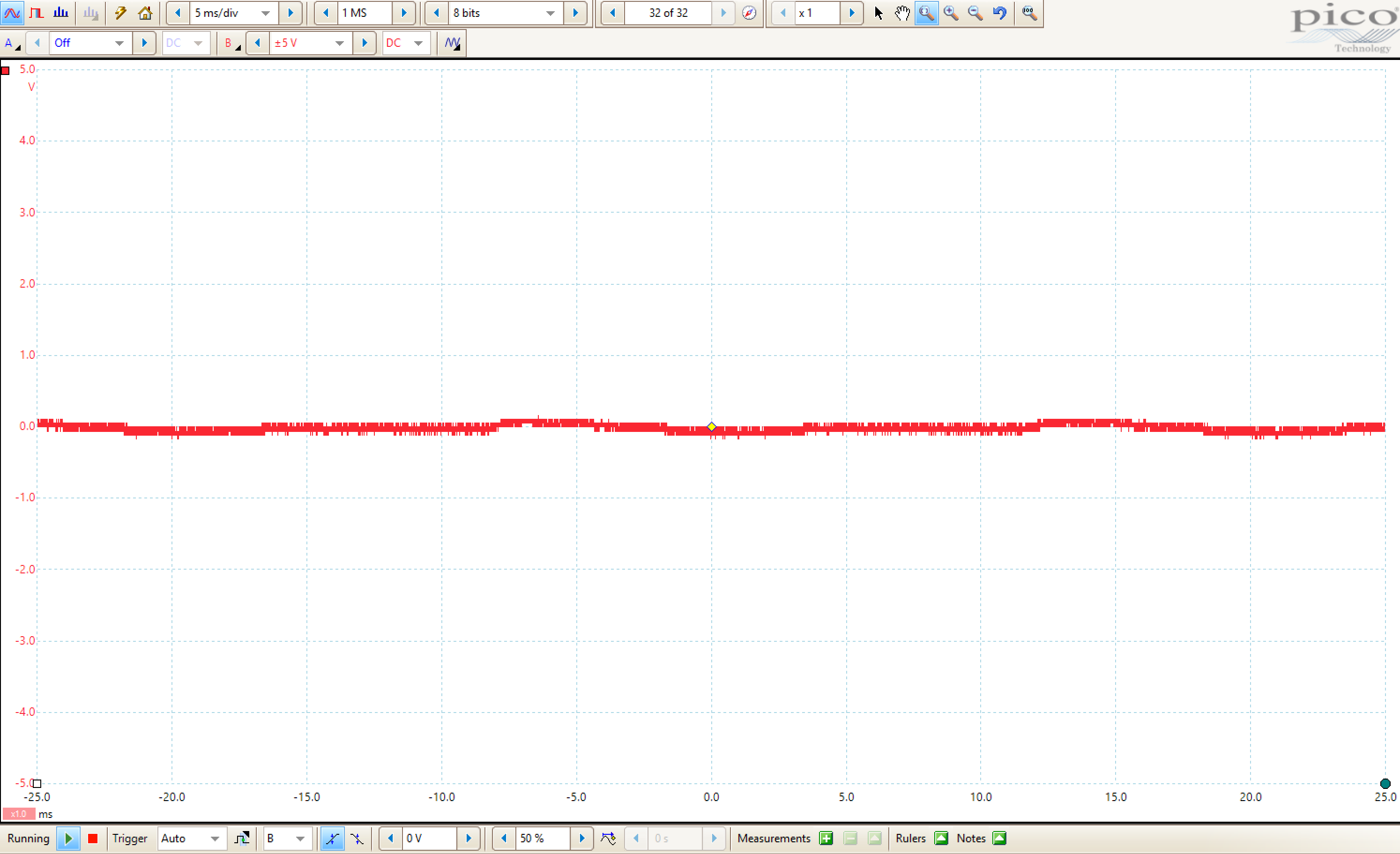
Fig 4: ADC_RDY signal from the AFE breakout board - Direct measurement on ADC_RDY pin on breakout board.

Here is the schematic that I used to build a AFE + SFH custom board.

So anyone has come across with the above-mentioned issues before, please help me out. I would really appreciate your help.

Thank you in advance.

  • Hello Vinh,

    Welcome to TI E2E forum.

    The board schematics of the HR3 development kit and the break out board schematics look the same.
    Can you please clarify if they are the same or different?
    Also based on the schematics, it seems like INM is shorted to 3.3V and also TX2, TX3, RESET and CLK seem to be shorted to GND.

    From the AFE + SFH custom board, do you notice the SFH7050 LEDs turn on after configuring the AFE?
  • Hi Praveen,
    Thank you for your reply.
    1. My breakout board and HR3 development kit are identical.
    2. I dont think INM is shorted to 3.3V and TX2, TX3, RST and CLK are shorted to the GND. I know the schematics is vague, however, I could turn on SFH7050 LEDs from the AFE with just TX1. Tx2 and Tx3 could not drive the rest of LEDs even I configured the designated registers correctly.

    Regards,
    Vinh
  • Hi Vinh,

    Can you check the presence of the diode on TX2,TX3 and ADC_RDY pins?

    Regards,
    Prabin
  • Hi Prabin,

    I currently do not have the diode on TX2, Tx3 and ADC_RDY pins.

    Is the presence of diode just only for protection purpose ? I am not quite sure how presence of diode would be working in this case.

    Regards,

    Vinh Thuan Tran
  • Hi Vinh,

    I was referring to the ESD protection diodes that are inside the AFE4404.
    So you just have to verify the presence of the diodes on above mentioned pins.

    Regards,
    Prabin
  • HI Prabin,
    I am still unsure about the presence of the diodes inside AFE4404.
    Can you give me more details or instructions about it ?

    Regards,
    Vinh
  • Hi Vinh,

    Most of the pins in an IC have internal ESD diodes.
    We can use this information to verify that the device is soldered correctly by measuring the voltage across these diodes.
    You can use multimeter in diode mode , connect the positive terminal to ground of the board.
    Now if you connect the negative terminal to above mentioned pins you should see a voltage ( 0.4 to 0.7V). If you don't see the voltage that means these pins are not connected to board and you have to re-solder the device.


    Regards,
    Prabin