This thread has been locked.

If you have a related question, please click the "Ask a related question" button in the top right corner. The newly created question will be automatically linked to this question.

IWR1443: DFP example code on external Host not running any OS

Part Number: IWR1443
Other Parts Discussed in Thread: IWR1243, UNIFLASH, AWR1243, AWR1443

Hello,

I have tried to port the DFP example code <mmwavelink_example> in DFP version 01_00_00_01, to a STM32 microcontroller, but unfortunately I have some issues with the implementation so the code doesn't really work as expected.

I am using an IWR1443, to which I have loaded the "xwr12xx_masterss.bin" and the "xwr12xx_xwr14xx_radarss.bin", so the IWR1243 is emulated. These bins are also found in the DFP library.

The SPI communication and the SPI_HOST_IRQ seems to work, since the STM32 MCU is receiving asyncronous events from the IWR1443 chip after the CNYS writes and the intitial messages from the IWR1443 chip is sent with correct checksum.

The call to "MMWL_powerOnMaster"  returns OK

and MMWL_setDeviceCrcType also return OK

but the call to MMWL_rfEnable returns with a TIMEOUT error.

I have analyzed the messages written and read by the STM32 MCU to power up the RF (in MMWL_rfEnable) and it looks okay, see below.

But one thing that seems a little strange is that in the example code it seems like we are waiting for an ASYNC message saying that RL_DEV_AE_RFPOWERUPDONE_SB (see MMWL_asyncEventHandler), but the message read from the IWR1443 after the AWR_DEV_RFPOWERUP_MSG command (see below), does not have a ASYNC message class, but a RESPONSE message class (yellow below), i.e. the "rlDriverAsyncEventHandler" will not be called in the function "rlDriverMsgCmdReply" and therefore will never mmwl_bStartComp be set to 1 in MMWL_asyncEventHandler.

Is this a bug or have I done something wrong?

In my STM32 implementation I am not using any OS and it was therefore not obvious how to implement some of the rlosi*** functions. For example I have just immediate call to pEntry(pValue) in the function "rlOsiSpawn" Is that Okay?.

I would really appreciate an example implementation using the DFP for an external host, which is not using any OS.

BR

Haakan

--- WRITE 22 BYTES ---
0x0034 /* SYNC => master to slave indicating a new command */
0x0012 
0x0021 
0x0043 
0x0005 /* OPCODE */
0x0080 0x8005 => DIRECTION = 0101 (Host to Master), MSGTYPE = 00 (COMMAND), MSGID = 0x200 (AWR_DEV_RFPOWERUP_MSG)
0x0012 /* MSGLEN */
0x0000 len = 18
0x0000 /* FLAGS */
0x0010 0x1000 => RETRY = 00 (New message), ACKREQ = 00 (ACK), PROT_VER = 0, CRC = 00 (Append CRC), CRCLEN = 00 (16bit), SEQNUM = 1
0x0000 /* REMCHUNKS */
0x0000 0
0x0001 /* NSBC */
0x0000 1
0x00E7 /* CHECKSUM */
0x006F CRC = 0x6FE7 (Stämmer!)
0x0000 /* SBLKID */
0x0040 0x4000 = AWR_DEV_RFPOWERUP_SB
0x0004 /* SBLKLEN */
0x0000 0x4 = 4 bytes
0x0000 
0x00DA 

--- WRITE 16 BYTES ---
0x0078 /* Write CNYS => External Host is ready to receive message */
0x0056 
0x0065 
0x0087 
0x00FF 
0x00FF 
0x00FF 
0x00FF 
0x00FF 
0x00FF 
0x00FF 
0x00FF 
0x00FF 
0x00FF 
0x00FF 
0x00FF 

--- READ 4 BYTES ---
0x00FF 
0x00FF 
0x00BA /* Sync Start */
0x00DC 

--- READ 4 BYTES ---
0x00CD 
0x00AB /* Sync End */
0x0016 /* OPCODE */
0x0080 0x8016 => DIRECTION = 0110 (Master to Host), MSGTYPE = 01 (RESPONSE), MSGID = 0x200 (AWR_DEV_RFPOWERUP_MSG)

--- READ 10 BYTES  ---
0x000E /* MSGLEN */
0x0000 0xE = 14 bytes
0x000C /* FLAGS */
0x0010 0x100C => RETRY = 00 (New message), ACKREQ = 11 (NO_ACK), PROT_VER = 0, CRC = 00 (Append CRC), CRCLEN = 00 (16bit), SEQNUM = 1
0x0000 /* REMCHUNKS */
0x0000 
0x0000 /* NSBC */
0x0000 
0x00CF /* CHKSUM */
0x006F CRC = 0x6FCF (Stämmer!)

--- READ 2 BYTES ---
0x0026 /* CRC */
0x00B5 0x26B5

---- WRITE 16 BYTES ----
0x0078  /* Write CNYS => External Host is ready to receive message */
0x0056 
0x0065 
0x0087 
0x00FF 
0x00FF 
0x00FF 
0x00FF 
0x00FF 
0x00FF 
0x00FF 
0x00FF 
0x00FF 
0x00FF 
0x00FF 
0x00FF 

  • Hakan,

    Your request has been forwarded to dfp expert. We'll let you know when we get back some response.

    Thanks and Regards,
    Michelle
  • Hi Michelle,

    In case you are not using OS at Host then you need to invoke a non-OS-Task function, where this function calls the spawned API which may have added from mmWaveLink while getting Async Event from AWR12xx.

    In OS environment this context switching is taken care by the OS itself so there you don't need to call the above-mentioned function.

    Here is the psuedo code for Non-OS spawn and MainLoopTask-

    int MMWL_rfEnable(unsigned char deviceMap)
    {
    int retVal = RL_RET_CODE_OK, timeOutCnt = 0;
    retVal = rlDeviceRfStart(deviceMap);
    while (mmwl_bStartComp == 0U)
    {
    rlNonOsMainLoopTask();
    rlAppSleep(1); /*Sleep 1 msec*/
    timeOutCnt++;
    if (timeOutCnt > MMWL_API_RF_INIT_TIMEOUT)
    {
    retVal = RL_RET_CODE_RESP_TIMEOUT;
    break;
    }

    }

    /* Non-OS Spawn function for reference */

    rlInt32_t  rlNonOsSpawn(RL_P_OSI_SPAWN_ENTRY pEntry, const void* pValue, rlUInt32_t flags)

    /* Store pEntry (function pointer to be spawned) and pValue (argument for Spawned function)  in some global variable. */

    }

    /* NonOsMainLoopTask for your reference */

    rlNonOsRetVal_t rlNonOsMainLoopTask(void)
    {

    /* Fetch the global variable for Spawn function pointer stored in rlNonOsSpawn */

    /* If it's not NULL then call that function with argument paramter */

    }

    Host needs to call 'rlNonOsMainLoopTask' whenever it's expecting any Async Event message from Device.

    Regards,

    Jitendra

  • Jitendra,

    I understand, but the question is then: When should you expect an asynchronous message from the chip?

    An alternative solution could be to use a timer ISR for the handling of the spawned function, but it’s not clear to me if the spawned function should be called once or repeatedly until the spawned function has been set to NULL. Will the driver “unspawn” the spawned function by setting the function  pointer to NULL, when the function not should be called any longer?

    BR Haakan

  • Dear Haakan,

    Spawn function is basically context switch. This is called from interrupt context and is expected to execute in different context.

    Since in No OS environment, you don't have multiple task, you need to execute the spwan function from main task/Timer ISR as you mentioned.

    rlDevicePowerOn, rlDeviceRfStart and rlRfInit APIs have associated Async event and is recommended to wait for such Async event before proceeding to next API as it is demonstrated in example code.

    Beyond that, in your main task, you can check for any ASYNC event periodically. These are basically then some reports about the status of device.

    Regards,

    Kaushal

  • Kaushal,

    Thanks for your response.

    It is becoming more clear, but I still have some questions.

    - Should the spawn function be called repeatedly or just once in “the different context”?

    - If repeatedly: How do you figure out when you should stop calling the function? I am thinking of an implementation in a Timer ISR. Should the spawned function be called until the function pointer is NULL?

    - You wrote “in the main task, you can check for any ASYNC events periodically”, but the question is: How do I do that? By calling the spawned function OR are there any other mmwave function you can use?

    - How is the spawned function related to the ASYNC event? Will the ASYNC event spawn the function? Will the spawned function call the rlDriverAsyncEventHandler?

    What documentation describe all these details, so I can write a driver for a NonOS software running in an external Host?

    BR Haakan
  • Dear Haakan,

    Please find my answers inline [Kaushal]

    - Should the spawn function be called repeatedly or just once in “the different context”?

    [Kaushal]: Just Once.

    - You wrote “in the main task, you can check for any ASYNC events periodically”, but the question is: How do I do that? By calling the spawned function OR are there any other mmwave function you can use?

    [Kaushal]: In the main function, you should just check if Spawn Callback is called and if yes, execute the Entry Function. Entry function would take care of receiving the ASYNC event.

    - How is the spawned function related to the ASYNC event? Will the ASYNC event spawn the function? Will the spawned function call the rlDriverAsyncEventHandler?

    [Kaushal]: As explained above, Application Main Task/Timer ISR, calls the Entry function in Spawn callback. The Entry function receives the ASYNC event and call rlDriverAsyncEventHandler.

    What documentation describe all these details, so I can write a driver for a NonOS software running in an external Host?

    [Kaushal]: Porting Guide in API documentation talks about the OS abstraction but no example code is available for Non OS

    API document: C:\TI\<mmwave_dfp_ver>\ti\control\mmwavelink\docs\doxygen\html\index.html

    Regards,

    Kaushal

  • Thank you Kausal,

    I have changed my implementation according to your recommendations, but I still doesn't get the ASYNC event <0x5001 – AWR_AE_DEV_RFPOWERUPDONE_SB> from the device. Since I never get this event, the MWM_Example code times out waiting for mmwl_bStartComp = 1 in the function "MMWL_rfEnable".

    The only event I get is <0x5000 – AWR_AE_DEV_MSSPOWERUPDONE_SB> and this event I get several times before the timeout.

    Could it be some error in the binaries I have downloaded with UniFlash. Note I have not enabled flashing over SPI.

    I have also noted that I get a very strange event from the chip once at every startup trial:

    NORMAL EVENT
    ============

    1) SPI_HOST_INTERRUPT Received

    2) Data written to IWR1443
    0x78 
    0x56 
    0x65 
    0x87 
    0xFF 
    0xFF 
    0xFF 
    0xFF 
    0xFF 
    0xFF 
    0xFF 
    0xFF 
    0xFF 
    0xFF 
    0xFF 
    0xFF 

    3) Data read from IWR1443
    0xFF 
    0xFF 
    0xBA 
    0xDC 

    4) Data read from IWR1443
    0xCD 
    0xAB   => SYNC READ
    0x36 
    0xA0 

    5) Data read from IWR1443
    0x26 
    0x00 
    0x0C 
    0x00 
    0x00 
    0x00 
    0x01 
    0x00 
    0x96 
    0x5F 

    6) Data read from IWR1443
    0x00 
    0x50  => SBLKID  = AWR_AE_DEV_MSSPOWERUPDONE_SB   
    0x18 
    0x00 
    0xF2 
    0x37 
    0x02 
    0x00 
    0x00 
    0x00 
    0x00 
    0x00 
    0x00 
    0x00 
    0x00 
    0x80 
    0x00 
    0x00 
    0x00 
    0x00 
    0x00 
    0x00 
    0x00 
    0x00 

    7) Data read from IWR1443
    0xF8 
    0x57 


    STRANGE EVENT
    =============


    1) SPI_HOST_INTERRUPT Received

    2) Data written to IWR1443
    0x78 
    0x56 
    0x65 
    0x87 
    0xFF 
    0xFF 
    0xFF 
    0xFF 
    0xFF 
    0xFF 
    0xFF 
    0xFF 
    0xFF 
    0xFF 
    0xFF 
    0xFF 

    3) Data read from IWR1443
    0xFF 
    0xFF 
    0xA5 
    0x41 

    4) Data read from IWR1443
    0x00 
    0x00 
    0xFF 
    0xFF 

    5) Data read from IWR1443
    0x00 
    0x00 
    0xFF 
    0xFF 

    6) Data read from IWR1443
    0x00 
    0x00 
    0xFF 
    0xFF 

    7) Data read from IWR1443
    0x00 
    0x00 
    0xFF 
    0xFF 

    8) Data read from IWR1443
    0x00 
    0x00 
    0xFF 
    0xFF 

    9) Data read from IWR1443
    0xFF 
    0xFF 
    0xBA 
    0xDC 

    10) Data read from IWR1443
    0xCD 
    0xAB            => SYNC READ
    0x36            
    0xA0            => OPCODE

    11) Data read from IWR1443
    0x22 
    0x00           => MSGLEN
    0xFF 
    0xFF           => ???? Should be FLAGS
    0xFF 
    0xFF           => ???? Should be REMCHUNKS
    0xFF          
    0xFF           => ???? Should be NSBC
    0xFF          
    0xFF           => ???? Should be CHECKSUM

  • Dear Haakan,

    I think the Strange Event is due to multiple trigger of Interrupts for same event. Can you confirm that you have configured the interrupt for only rising edge of GPIO.

    Also the communication on SPI due to Strange event is mostly stale data read. Can you also confirm below:

    SPI word size = 16bit
    CS Hold = False
    Look for SPI configuration/constraints in DFP user guide

    At step3 (Normal Event)
    3) Data read from IWR1443
    0xFF
    0xFF
    0xBA
    0xDC
    I see 2 additional Bytes 0xFF 0xFF. Have you implemented rlDeviceWaitIrqStatus, rlTimerCbs_t.rlDelay callbacks. Please confirm

    Regards,
    Kaushal
  • Kaushal,

    Thanks for your help!

    I have verified the external IRQ setup and it is only configired for RISING edge, so that is not the problem, but I found an issue in my ReadSPIData routine, so now the communication looks a better, with no strange messages. Since the toggling of the CS and the timing requirements are a little special for this chip I cannot use the build-in SPI hardware for controlling the CS, so I had to do this control manually with a delay between the CS and the SPI_Send/Receive. I have to figure out how this could be done with a DMA transfer later...

    With these changes the code doesn't go in timeout in MMWL_rfEnable anymore, which is very good. Further the software passes by MMWL_basicConfiguration without any issues.

    But unfortunately the software gives a TIMEOUT in the function MMWL_rfInit.

    Below is my analysis of the communication and external interrupts. (Only writes/reads after the RF_INIT is presented)

    As you can see the Host never receives any AWR_AE_RF_INITCALIBSTATUS_SB events, but instead it receives a couple of AWR_AE_DEV_MSSPOWERUPDONE_SB events.

    Any help is really appreciated...

    /* Host writes to IWR1443 */
    0x34 
    0x12 
    0x21 
    0x43 /* SYNC => master to slave indicating a new command */
    0x81 /* OPCODE */
    0x01  0x0181 => => DIRECTION = 0001 (Host to BSS), MSGTYPE = 00 (COMMAND), MSGID = 0x202 (AWR_RF_INIT_MSG)
    0x12 
    0x00 
    0x00 
    0x90 
    0x00 
    0x00 
    0x01 
    0x00 
    0x6B 
    0x6E 
    0xC0  /* SBLKID */
    0x00  0x00C0 – AWR_RF_INIT_SB
    0x04 
    0x00 
    0x7C 
    0xFA 


    <<<<SPI HOST INTERRUPT>>>>

    /* Host writes to IWR1443 */
    0x78 
    0x56 
    0x65 
    0x87 
    0xFF 
    0xFF 
    0xFF 
    0xFF 
    0xFF 
    0xFF 
    0xFF 
    0xFF 
    0xFF 
    0xFF 
    0xFF 
    0xFF 


    /* Host reads from IWR1443 */
    0xBA 
    0xDC 
    0xCD 
    0xAB 

    /* Host reads from IWR1443 */
    0x92  /* OPCODE */
    0x01  0x0192 => DIRECTION = 0010 (BSS to HOST), MSGTYPE = 01 (RESPONSE), MSGID = 0x06 (AWR_RF_INIT_MSG)
    0x0E  /* MSGLEN */
    0x00  14 bytes
    0x00  /* FLAGS */
    0x90  0x9000
    0x00 
    0x00 
    0x00 
    0x00 
    0x5F 
    0x6E 

    /* Host reads from IWR1443 */
    0x34 
    0xF1 


    <<<<SPI HOST INTERRUPT>>>>

    /* Host writes to IWR1443 */
    0x78 
    0x56 
    0x65 
    0x87 
    0xFF 
    0xFF 
    0xFF 
    0xFF 
    0xFF 
    0xFF 
    0xFF 
    0xFF 
    0xFF 
    0xFF 
    0xFF 
    0xFF 

    /* Host reads from IWR1443 */
    0xBA 
    0xDC 
    0xCD 
    0xAB 

    /* Host reads from IWR1443 */
    0x36  /* OPCODE */
    0xA0  0xA036 => DIRECTION = 0110 (Master to Host), MSGTYPE = 11 (ASYNC), MSGID = 0x280 (AWR_DEV_ASYNC_EVENT_MSG)
    0x26 
    0x00 
    0x0C 
    0x00 
    0x00 
    0x00 
    0x01 
    0x00 
    0x96 
    0x5F 

    /* Host reads from IWR1443 */
    0x00  /* SBLKID */
    0x50  0x5000  ( = AWR_AE_DEV_MSSPOWERUPDONE_SB)
    0x18  /* SBLKLEN /*
    0x00 
    0xF2  /* MSS_POWERUP_BIST_STATUS_FLAGS */
    0x37 
    0x02 
    0x00 
    0x00  /* POWERUP_TIME */
    0x00 
    0x00 
    0x00 
    0x00 
    0x00 
    0x00 
    0x80 
    0x00 
    0x00 
    0x00 
    0x00 
    0x00 
    0x00 
    0x00 
    0x00 

    /* Host reads from IWR1443 */
    0xF8 
    0x57


    <<<<SPI HOST INTERRUPT>>>>

    /* Host writes to IWR1443 */
    0x78 
    0x56 
    0x65 
    0x87 
    0xFF 
    0xFF 
    0xFF 
    0xFF 
    0xFF 
    0xFF 
    0xFF 
    0xFF 
    0xFF 
    0xFF 
    0xFF 
    0xFF 

    /* Host reads from IWR1443 */
    0xBA 
    0xDC 
    0xCD 
    0xAB 

    /* Host reads from IWR1443 */
    0x36 
    0xA0 
    0x26 
    0x00 
    0x0C 
    0x00 
    0x00 
    0x00 
    0x01 
    0x00 
    0x96 
    0x5F 

    /* Host reads from IWR1443 */
    0x00  /* SBLKID */
    0x50  0x5000  ( = AWR_AE_DEV_MSSPOWERUPDONE_SB)
    0x18 
    0x00 
    0xF2  /* MSS_POWERUP_ BIST_STATUS_ FLAGS */
    0x37 
    0x02 
    0x00 
    0x00 
    0x00 
    0x00 
    0x00 
    0x00 
    0x00 
    0x00 
    0x80 
    0x00 
    0x00 
    0x00 
    0x00 
    0x00 
    0x00 
    0x00 
    0x00 

    /* Host reads from IWR1443 */
    0xF8 
    0x57 


    <<<<SPI HOST INTERRUPT>>>>


    /* Host writes to IWR1443 */
    0x78 
    0x56 
    0x65 
    0x87 
    0xFF 
    0xFF 
    0xFF 
    0xFF 
    0xFF 
    0xFF 
    0xFF 
    0xFF 
    0xFF 
    0xFF 
    0xFF 
    0xFF 

    /* Host reads from IWR1443 */
    0xBA 
    0xDC 
    0xCD 
    0xAB 

    /* Host reads from IWR1443 */
    0x36 
    0xA0 
    0x26 
    0x00 
    0x0C 
    0x00 
    0x00 
    0x00 
    0x01 
    0x00 
    0x96 
    0x5F 

    /* Host reads from IWR1443 */
    0x00  /* SBLKID */
    0x50  0x5000  ( = AWR_AE_DEV_MSSPOWERUPDONE_SB)
    0x18 
    0x00 
    0xF2  /* MSS_POWERUP_BIST_STATUS_FLAGS */
    0x37 
    0x02 
    0x00 
    0x00 
    0x00 
    0x00 
    0x00 
    0x00 
    0x00 
    0x00 
    0x80 
    0x00 
    0x00 
    0x00 
    0x00 
    0x00 
    0x00 
    0x00 
    0x00 

  • Hello Hakan,
    Looks like after rf_init device is going for reset and Host is getting MSSPOWERUPDONE_SB message.
    This could happen if power supply is not proper on different supply rails of device as at rf_init command device does multiple calibrations which takes more power from supply.

    Could you please confirm the AWR board type either it is EVM or custom board? If it is custom board with xWR1443 chip on it then we would request to check for power supply specification.

    Power supply specification is given under section 5.5 of AWR1243 datasheet (www.ti.com/.../awr1243.pdf)


    Regards,
    Jitendra
  • Jitendra,

    Thanks for your respons.

    I am using a custom board, but I have not had any supply issues when I run other code in the IWR1443 chip, which also includes calibration. For example I am running a modified mmw demo in the chip with success.

    BR,

    Håkan 

  • Jitendra,

    Is there any way to check whether the MSS or BSS has restarted? (It would have been nice with some status registers...)

    I tried to disable all calibrations with the rlRfInitCalibConfig-command, but I couldn't see any difference, i.e. I still get TIMEOUT waiting for (mmwl_bRfInitComp != 0)

    I also tried reading the RfBootStatus with the rlGetRfBootupStatus-command, after the RfInit TIMEOUT, but the function does not return, i.e. it seems to be stucked in this function, which feels a little strange. Before the call to rlRfInit it returns with reasonable values.

    Does the MSS binary configure the PMIC (over I2C)?

    BR

    Haakan
  • Hello Haakan,

    Async Event message with sub-block-ID [0x5000]  device sends only on  device powerOn, which in your case Host is receiving after rf-Init command again.

    Is it possible to connect JTAG to AWR1443 device and read '0xFFFFE1EC' register? This is the status register which shows RadarSS powerUp status.

    If RadarSS is powered On [rlDeviceRfStart] then this register will have the value '0x000F0028'.

    Try to read this register post rf-init command when Host is timed out for reading Async Event, register value '0x00000028' will prove device reset event.

    MSS binary doesn't configure PMIC (over i2c).

    Please confirm the above register value then we can debug further with a comparison to SDK AWR1443 application.

    Regards,

    Jitendra

  • Jitendra,

    Since I only have the MSS and BSS binaries (found in mmwave_dfp_01_00_00_01\firmware), my debug possibilities are quite limited.

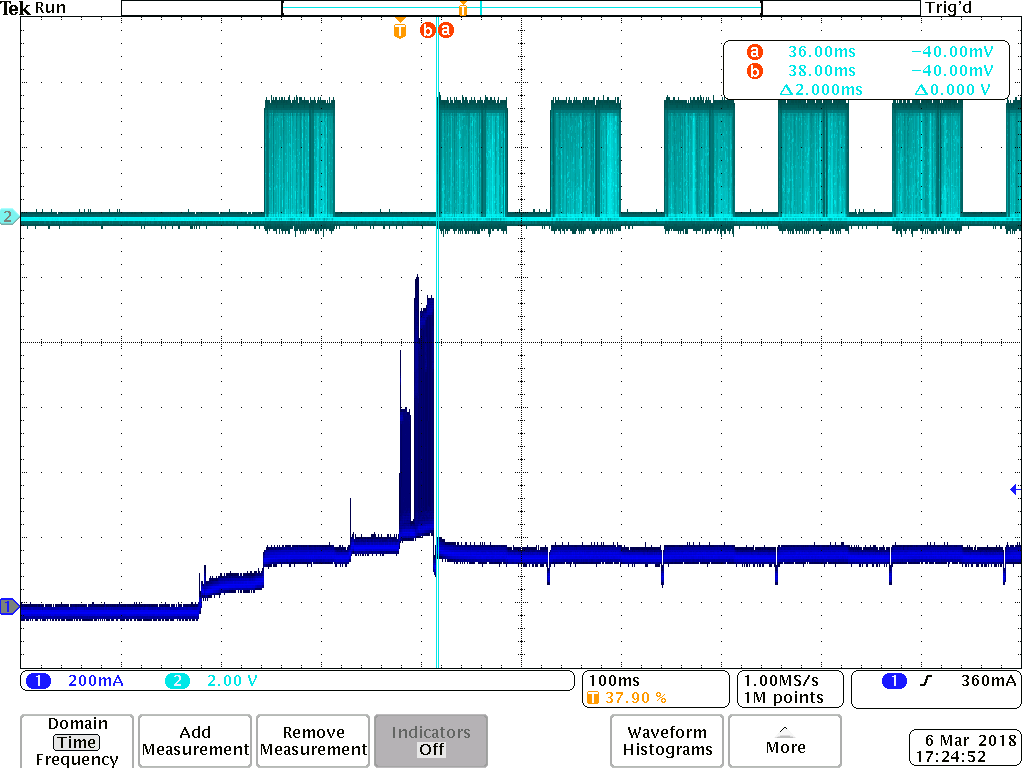
    I did some measurements with an oscilloscope, see below.

    The blue curve is the current consumption during the startup of the IWR1443 chip.

    The cyan curve is the QSPI communication with the external flash

    The high current consumption, that starts at the trigger point (T), I guess comes from the calibration of the chip (done in MMWL_rfInit). The calibration seems to go on for a while, but it is quite obvious that the chip is restarted during this calibration/verification since the QSPI communication shows that the SW is read from the flash.

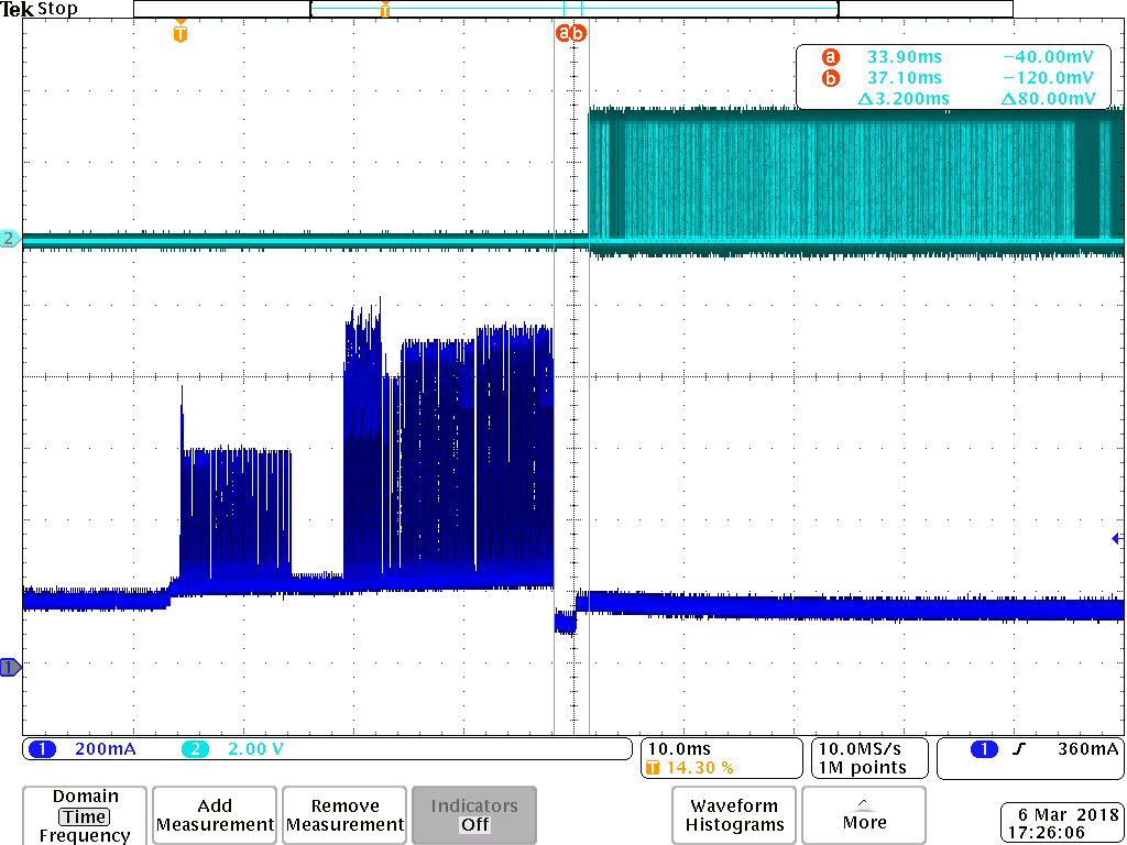
    The other oscilloscope plot is a zoomed version of the first one, centered at the position where the chip seems to reboot. Here you can see that the SW load starts approx 3 ms after the last spike in the current consumption.

    I also verified the supply on all rails and couldn't see any voltage drops, that could explain the restart of the chip.

    What else except the voltage drops could explain the restarts?

    Watchdog Reset?

    Fatal exception Reset?

    What I also think is a little strange, is that when the chip has restarted once it seems to go into a reset loop, with a reset every 125 ms.

    BR,

    Haakan

  • Jitendra,

    I have done some furter investigations and have found:

    With the binaries in "mmwave_dfp_01_00_00_01\firmware"

    - If I just enable the PMIC and release the reset to the IWR1443 (i.e. I don't start the mmwavelink_example) the IWR1443 will restart automatically approximately 40 ms after the software is loaded.

    - After the restart the IWR1443 will restart again after 40 ms and so on, and so on...

    - With the binaries in "mmwave_dfp_00_09_01_06\firmware" I don't see any resets.

    My theory is that you have to request data from MSS. If you don't the IWR1443 will reboot after approx 40 ms.

    - If I run the "mmwavelink_example" I get a TIMEOUT in "MMWL_rfInit", as I have written before, but if I add a call to "rlDeviceGetMssVersion" after 20 ms in the loop, the MMWL_rfInit will return with RL_RET_CODE_OK, but this "fix" only delays the reboot, since the code is locked-up in "MMWL_chirpConfig" instead.

    Do you have any comments on this?

    Can you please verify that the binaries in the folder "mmwave_dfp_01_00_00_01\firmware" have a good status.

    BR

    Haakan

  • Hello Haakan,
    To identify which calibration is causing this reset when you call rf_init() API, could you follow this sequence?

    1. Before calling rf_init(), Invoke rlRfInitCalibConfig(DEVICE_MAP, &rfInitCalib) where you need to disable all calibration in the parameter which is passed to this API.
    2. Now invoke rf_init() API.

    Try above experiment by enabling one calibration at a time (rlRfInitCalConf_t rfInitCalib) and call rlRfInitCalibConfig, check on which point device goes for a toss.

    Along with this can you give us power supply (all rails) details which you are feeding to device.


    Regards,
    Jitendra
  • Jitendra,

    I have already tried this, but it didn't make any difference. The IWR1443 is restarted even if all calibrations are disabled.

    I have also downloaded the (mmwave_dfp_01_00_00_01) binaries in in one of our EVM's and the IWR1443 goes into a reset loop when power is turned on.

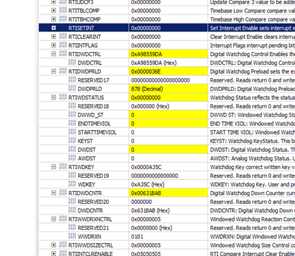
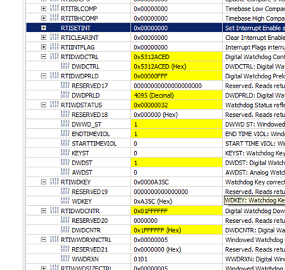
    My guess is that you have enabled the watchdog in the MSS software (with a timeout of approx 40ms). It seems like the watchdog only is trigged when you communicate with the IWR1443 (MSS) and therefore the IWR goes into this reset loop.

    Does this make sense?

    View of registers in debugger (EVM connected) => Watchdog is enabled with timeout approx 36ms...

    Another view (EVM connected) => The watchdog has timed out...

    BR,

    Haakan

  • Hakan,

    Let us know if you still have question.

    Thanks and Regards,
    Michelle
  • Liu,


    If you read the posts you will see that there are several questions that not have been answered, e.g. my last post, so the answer to your question is YES.


    I still cannot perform measurements with the DFP.


    BR


    Haakan
  • Hi Haakan,

    Sorry for the delay. We've been working on this. This seems to be a problem associated with dfpv1.0. Is it possible to dfpv0.9 instead?

    Thanks

    Regards,

    Michelle