This thread has been locked.

If you have a related question, please click the "Ask a related question" button in the top right corner. The newly created question will be automatically linked to this question.

PGA460: Application Questions

Part Number: PGA460
Other Parts Discussed in Thread: TDC1000, EVM430-FR6047, MSP430FR6047

Dear TI Team.

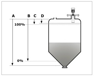
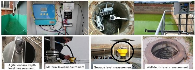
I am going to develop a flow level meter with Ultra Sonic.

I am reviewing the PGA460, but I would like to see if there is a history of design in the flow level measuring instrument.

And on the PGA460 there is no pin to sense the temperature of the ultrasonic transducers. Can you tell me how to implement it?
In TDC1000, pin is designed to detect the temperature of ultrasonic transducers with RTD pin.

Please let me know if there is another suitable solution.

Thanks.

  • Hi Chun,

    The PGA460 is only suitable for air-coupled ultrasonic measurements. This means the transmission medium for sound to propagate through is exclusive to air due to the low supported transducer frequency ranges of 30k-80kHz and 180k-480kHz.

    I recommend the TDC1000, which is designed for liquid-coupled ultrasonic measurements because it can support a higher transducer frequency range (31.25kHz to 4MHz). The MHz transducer range is most suitable for transmitting sound waves through liquids. Yes, temperature can be monitored by the TDC1000 via the RTD pin.

    Another integrated alternative is the MSP430FR6047, which show cases Ultrasonic Water Flow Metering using their MSP430FR6047 Ultrasonic Sensing Evaluation Module (EVM430-FR6047).
  • Dear Akeem,

    Simply put, as shown below, you want to measure the level of a liquid such as a water tank.

    So, PGA460 seems to be possible even with products that are air-coupled.

    We plan to use a high voltage transducer with a specification of about 600V.

    Can you tell me which product is better suited to you by referring to the picture below?

  • Hello Chun,
    Yes, the PGA460 will be most suitable for tank-level measurements through air from the top of the tank as shown in your images.

    600V transducer compatibility will not be an issue with the PGA460, though you may not need to drive the transducer at its maximum rating depending on the maximum required distance.
    What is the frequency of the 600V transducer? I ask because it is important to consider what the minimum and maximum detectable distance, which is strongly dependent on the transducer frequency. Low frequency = longer range, but worse short range minimum.

  • Dear Akeem,

    Thank you for answer.

    - Ultrasonic frequency: about 40KHz ~ 60KHz
    - Ultrasonic transducer: Airmar product standard
    - Measuring distance: approx. 10 m (typical measuring distance for 2-Wire products)
    - Measuring method: It is a general non-contact type level transmitter that displays the current output and measuring distance by measuring the distance from the air medium in the tank to the measuring medium.

     The ultrasonic wave should measure and compensate the temperature inside the transducer because the transmission speed changes according to the temperature and humidity in the tank. How should the temperature be compensated when designing with PGA460? Can you provide a solution?

    Thanks.
  • Hi Chun,

    If you are interested in a 2-Wire solution for the PGA460, refer to the following E2E discussion: e2e.ti.com/.../618668

    You are correct that temperature will change the speed of sound, and is the predominant environmental factor to do so. The equation to solve for the speed of sound as a function of temperature is as follows:
    SpeedOfSound(m/s) = 331m/s + [0.6m/s/°C * Temperature(°C)]

    The PGA460 offers an integrated temperature sensor to monitor die-temperature. However, this temp sensor can also be used to monitor the ambient temperature as described in section 7.3.11 Temperature Sensor and Temperature Data-Path of the datasheet:
    Without calibrating TEMP_GAIN and TEMP_OFF, the ambient temperature can be approximated from the die temperature reading using Equation 8:
    TAmbient (°C) = TDie - [RθJA × (VPWR × IVPWR_RX_ONLY)]
    where
    • RθJA(°C/W) is the Junction-to-ambient thermal resistance of 96.1°C/W.
    • VPWR (V) is the input voltage.
    • IVPWR_RX_ONLY(mA) is the supply current from VPWR pin during listen only mode of 12mA.

    When the time-of-flight results have been obtained, use the temperature compensated speed-of-sound value for conversion to distance: distance (m) = [speedOfSound (m/s) *timeOfFlight (s) ] / 2

    The attenuation of sound in air is affected by the relative humidity. Dry air absorbs far more acoustical energy than does moist air. This is because moist air is less dense than dry air (water vapor weighs less than air). The PGA460 does not include an on-board humidity sensor, but consider that humidity's impact on the speed-of-sound is negligible compared to temperature. Here is a related article on humidity's impact on the speed-of-sound for more details: sciencing.com/humidity-affect-speed-sound-22777.html
  • Dear Akeem.

    Thank you for answer.
    But I still could not understand the temperature compensation.
    The transducers we are going to use have thermal couplers.
    We know that you have to compensate according to the temperature of the transducer.
    I do not know how to connect this part PGA460.
    Can you check it?

    Thanks.
  • Hi Chun,

    Can you provide the specific part number of the transducer you are using? I am not familiar with transducers that have built-in thermal couplers. Most transducers are only two-pin devices (positive and negative terminals), which would be connected to the transformer's secondary pins as shown in datasheet "Figure 136. Transformer-Driven Method Schematic".

    The most important variable to note with regard to temperature is the change in the speed of sound. This has less to do with the behavior of the transducers, and more so with how speed propagates through air at varying temperature. As previously noted, you need to know temperature to properly convert time-of-flight to distance.

    Some transducers will also behave differently across temperature, which why it is important to characterize and optimize the settings of your transducer across temperature. In some cases, adding or removing a tuning capacitor in parallel to the transducer will help to calibrate the matching circuit beyond a certain temperature (refer to PGA460 datasheet section "7.3.9.2 Temperature Decoupling" for more details).
  • Dear Akeem.

    http://www.airmartechnology.com/uploads/AirPDF/ARK50THD.pdf

    The sensor we are going to use is the Spec of the link above.

    Can you check it?

    Thanks.


  • Hi Chun,

    Yes, the ARK50THD Airmar transducer is compatible with the PGA460 based on the resonant frequency and driving voltage requirement.

    The optional 10 KΩ thermistors for temperature compensation offered by Airmar is independent from the transducer connection. I assume additional leads will be made available in the mechanical housing for the thermistor connection. You will want to confirm with Airmar.

    Note, 1kV is the maximum driving voltage of this transducer. You may not need to drive the transducer up to 1kV to meet the performance. In the event 1kV is required, consider the following:

    The receiver current will be limited by the CINP cap. The impedance is set by this capacitor with the equation 4 from the PGA460 datasheet:

    So, the max current will be voltage seen during burst over this impedance. This current should be maximum ~15mA. So, for 1kV, the current at 80kHz with 33pF CINP will be ~16.58mA. CINP should be reduced by x10 for 1kVpp compared to 100Vpp.

  • Dear Akeem,

    What we are concerned about is the temperature change part.
    You may need to adjust the output depending on the temperature of the transducer.
    The reason for this is that if you measure 10m according to the temperature inside the tank, it may cause deviation.
    Can I adjust the gain for the output for the PGA460? In the datasheet, it seems that adjustments to the gain for INP are possible, but the gain for the output seems to be out of control.
    Then we need to use a transformer and separately design the power supply to the transformer to compensate for the temperature.
    We are also reviewing the PGA450 product. We confirmed that the PGA450 product has a built-in voltage regulator.
    I would like to know which of the PGA450 or PGA460 is more suitable for a solution such as a water tank.
    Or I would like to make sure that there is a chip for another part that is more appropriate.

    Thanks.
  • Hi Chun,

    The PGA460 driver output strength can be controlled with greater equivalent range and precision than the PGA450. Although the center-tap voltage to the transformer is fixed, the internal preset driver current limiting of the OUTA and OUTB sink pins serves as an equivalent to a varying center-tap voltage. The PGA460's driver current limit can be set from 50-491mA at 7mA increments for a total of 64 different combinations. When the driver current limit is at its maximum value of 491mA, a center-tap voltage of 8V and a transformer turns ratio of 1:1:10 (for example) will yield 160Vpp at the transducer. At 50mA and the same center-tap and turns ratio, only 40Vpp may be generated at the transducer.

    You can think of the driver current limit as your peak-to-peak (volume) knob for transducer driver voltage. Thus, if you want to get the maximum excitation voltage at the secondary, you set the driver current to 491mA. With a typical center-tap transformer with a turns-ratio of 1:1:10, and a center-tap voltage of 8V, you should expect to see a voltage of 160Vpp (+/- 80V). Let's say your transducer is only rated for 80Vpp, or you want to compensate drive strength based on temperature: with the same center-tap voltage, you can reduce the driver current limit to 200mA for example to generate a secondary voltage of ~80Vpp. Refer to the PGA460 Ultrasonic Module Hardware and Software Optimization appnote section 4.3 Current Limit to see how your peak drive strength is impacted. You'll notice increasing from 50-500mA is not linear; instead, it is more logarithmic, where the initial change in peak-to-peak is significant (50~200mA), but eventually saturates near the larger current limit (400~500mA). You'll need to experiment with the driver current limit to find the optimal settings based on your center-tap voltage and pulse count.

    I would not recommend the PGA450. VREG of the PGA450 only offers 16 options from 4.7 to 8.4V at 0.1V increments. In addition, VPWR must be at least 2 V above the selected VREG voltage. The greatest disadvantage of the PGA450's driver is that there is no primary-side low-side current limiting, and transients can reach upwards of 1~3A. Most transducers saturate with a primary sink current of ~500mA, so the rest of the energy is dissipated/wasted as heat at the transformer. This is why we set the driver current limit max to 500mA on the PGA460 and gave the current limiting feature four times more step resolution for precision driver control.