This thread has been locked.

If you have a related question, please click the "Ask a related question" button in the top right corner. The newly created question will be automatically linked to this question.

IWR1443BOOST: Capture Demo: How it works!

Part Number: IWR1443BOOST

Dear All,

I'm reading the mmWave SDK User Guide and it seems that Capture Demo is something interesting for having the data out of the board.

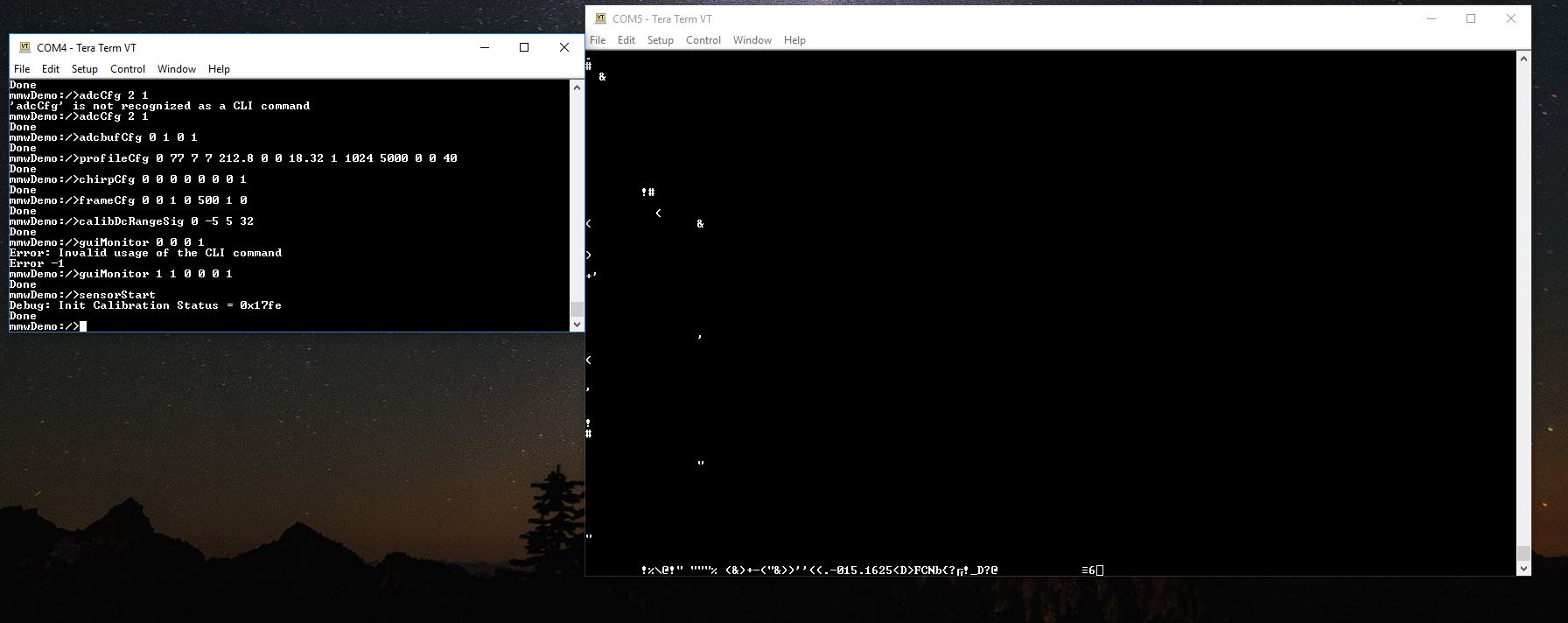
However, the guide is not clear for me and I don't understand how to reach the configuration shown in Figure at page 14 (Sec. 3.3.2)

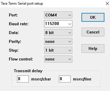
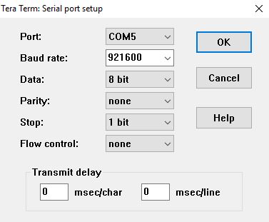
The guide says to open a teraterm or hyperterminal and connect the "User UART" Com port, but where can I find this tool?

More info about this tool are available somewhere? 

Many thanks in advance for your help,
Davide

  • Davide,

    You can use any terminal emulator program that allows you to access and write/read text to/from the COM ports on your computer. The mmWave SDK user guide mentions Tera Term as one option since it is a free, open-source terminal emulator program that you can download from the web. You should be able to find it by searching for "Tera Term" on Google. However, you can also use any other terminal program of your choice.

    Also, if you have any problems connecting to the EVM once you have Tera Term, please make sure to follow the instructions in the SDK user guide for selecting the correct COM port in Tera Term and also make sure the Tera Term Serial Port setup window has the Baud rate set to 115200.

    Please mark as answered if this resolves the issue or reply if more support is required.

    Best Regards,
    John
  • Dear John,

    it seems that it is not so simple. The SDK guide seems to be not complete and the connection always fails.

    Please, could you provide a step-by-step guide. This would help also other users of this Community.

    Many thanks,
    Davide

  • Davide,

    There is actually a step-by-step guide for the mmWave SDK capture demo already online at the following link:

    https://e2e.ti.com/cfs-file/__key/communityserver-discussions-components-files/1023/ADC-Data-Capture-SDK1.05-V1.00.pdf

    It is referenced in the last row of the table on the following E2E thread:

    https://e2e.ti.com/support/sensor/mmwave_sensors/f/1023/t/619401

    Please mark as answered if this resolves the issue or reply if more support is required.

    Regards,

    John

  • Dear John,

    many thanks for your kind help. However, I realize that probably my questions are not so clear.

    I try in the following to illustrate what I have done till now. I know that I'm close to the victory, but I failed at the last round.

    Please, have a look to my list below and, if you can, help me to understand where the error is.

    The steps I followed are listed below (please, send me an ACK for each step to be sure that the procedure is correct):

    1) Flashed the EVM with the *.bin files for the application "High Accuracy xWR14xx". The files are "xwr12xx_xwr14xx_radarss.bin" and "xwr14xx_high_accuracy_mss.bin".

    2) Power cycle the EVM without jumper SOP2.

    3) Open 2 sessions of TeraTerm: one for Application/User port and one for Data Port (in my case COM4 and COM5, respectively).

    4) Set the ports as follows (No other settings have been made, is it right?):

    5) On the COM4 terminal, I sent exactly the same configuration commands reported in the configuration file "profile_2de.txt", i.e.

    sensorStop

    flushCfg

    dfeDataOutputMode 1

    channelCfg 1 1 0

    adcCfg 2 1

    adcbufCfg 0 1 0 1

    profileCfg 0 77 7 7 212.8 0 0 18.32 1 1024 5000 0 0 40

    chirpCfg 0 0 0 0 0 0 0 1

    frameCfg 0 0 1 0 500 1 0

    calibDcRangeSig 0 -5 5 32

    guiMonitor 1 1 0 0 0 1

    sensorStart

    6) After the last command, the COM5 terminal starts to "move", but the visualized symbols are not the same as discussed in the thread you suggested to read.

    Please, could you help me to understand where is the error?

    For sake of completeness, this is what I see after "SensorStart:

  • Davide,

    The flow you described is not from the step-by-step capture demo guide and cannot be used with the capture demo.  I am guessing that the flow you described came from the High Accuracy demo support thread (IWR1443BOOST: LEVEL SENSOR: Radar Studio e how-to have the value of level out of the board)?

    The instructions for the capture demo use only the Application/User COM port (but not the Data COM port) and involve loading the capture demo binaries (not High Accuracy demo binaries) using CCS.  If you have issues when following the instructions in the capture demo guide, please confirm which section/slide number in the guide that you are having trouble with and I can try to assist.

    Regards,
    John

  • Dear John,

    You are right! The procedure described in High Accuracy demo support thread is exactly what is typically desired in real applications for sending configuration and receiving Data (e2e.ti.com/.../2455636

    In fact I realize that, currently, Capture Demo always needs of a PC and CSS software. This is a very particular case because typically the EVM is not connected in Debug mode, but in Functional Mode without a PC. When EVM is running, you can spoof COM Data port and wait for data to be captured by a Microcontroller, Arduino, RaspberryPI, etc.

    Capture Demo was my first idea for having data available, but actually it is limited for these applications. Do you agree? Or there is a trick for overcoming these limits?

    Currently, it seems that if the procedure illustrated above would represent the simplest way to achieve configurations and receive data and any user can use. However, as you can see, it doesn't work. It should work becasue the same binary works well with the web application "Fluid level" and "High Accuracy visualizers". Therefore, the data are effectively sent to the PC.
    Please, could you help me?

    Many thanks for everything.

    My best,
    Davide
  • Davide,

    The mmWave SDK capture demo allows you to capture a small amount (but at least one frame) of the raw Radar ADC data before it has been post-processed inside the device by the internal processing chain which performs the detection of objects based on the Radar data. The purpose of the demo is to allow customers to perform small captures of the raw Radar data to analyze and experiment with their own custom processing chains if desired during their system design. It is not intended to be used during normal operation as it does require a PC and CCS software and can only be used to get single captures at a time (i.e. it cannot perform continuous uninterrupted streaming of the data).

    The Fluid Level Transmitter and High Accuracy Range Measurement demos would be more appropriate examples for those types of applications. It looks like you are already receiving support for those demos on the other thread. If you have any more questions about the capture demo, please feel free to post them to this thread. Otherwise, please mark as answered if your capture demo questions are resolved.

    Thanks,
    John