This thread has been locked.

If you have a related question, please click the "Ask a related question" button in the top right corner. The newly created question will be automatically linked to this question.

Linux/OPT9221: opt9221 image

Part Number: OPT9221
Other Parts Discussed in Thread: OPT8241

Tool/software: Linux

Hi,

About opt9221 3D_ToF imaging problems:

I try to configure opt9221 in DVP mode. And I have some question:

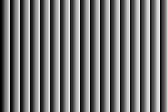
The firmware is loaded successfully, and the version number is read correctly. The OPT9221 initialization register configuration is completed. The OPT9221 operates at 9% integration time, the modulation frequency is 48Mhz, and the output mode is DVP mode, blk_size = blk_blank_size = 1280.However, the image is not displayed correctly.

What causes this problem?

Below is the image I collected:

  • if set phy_test_enable = 1 image is :

  • this Group by 8 (default) output data:
    0,0,0,0,0,0,0,0,0,0,0,0,0,0,0,0
    EC,5,71,1,D4,4,CF,C,CF,C,32,C,F5,B,5A,C
    0,0,0,0,0,0,0,0,0,0,0,0,0,0,0,0
    EC,9,13,2,30,B,CD,F,A5,3,5A,4,F6,3,A5,3
    ......
    Why both amplitude and ambient are zero
  • Please check your illumination to make sure it is transmitting; and check to make sure object is not too near to cause saturation.
    Also try run mac test and report the result.

    What are your other modulation related settings? mod_mx, mod_nx, mod_psx, etc., where 'x' is 1 or 2.

    -Larry
  • Hi LarryLi,

    After I set mac_test_enable = 1, the image is

  • CMOS is not imaging, with the phone flash direct exposure to the lens without any reaction;
    No other modulation related settings,and with reference to the OPT9221 initialization sequence you provided.
    Other registers are not set, are the default value.So we are not sure whether it is a hardware problem or a software problem.
  • hi Larry,
    My lighting circuit and the sensor is separate, may I ask in the absence of lighting, with strong light will have a reaction? Can COMS be imaged?
  • Hi Kevin,

    If you are flashing the 3D-TOF sensor with strong light, you will cause saturation.  That will lead to 0 ambient, and 0 amplitude.  Ambient is a 4-bit value (0-15), 15 is very low ambient, 0 is very strong ambient (saturated).  At high ambient, which represents "DC" component of incoming light, amplitude, which represent AC component riding on the DC (ambient), will have no head room to swing, hence the 0 amplitude.

    Have you tried without flashing and getting some images?

    -Larry

  • Hi Larry,

    I'm sorry to always trouble you, but we really need your support, please forgive me; Here are some of our problems:

    1, the speed of data output and HD triggering speed decreases with time, what is the reason?


    2, the lens with a filter, in the case of light irradiation without any reaction, the image looks messy, the data is output is incorrect or circuit noise?


    3, if phy_test_enable = 1, the output data is 0,0,1,2, ..., 255,0,1,2, ... 255, ... The data looks correct, but if phy_test_enable = 0, the output data is
    0
    0
    0
    0
    0xxxxxxxxx
    0xxxxxxxxx
    0xxxxxxxxx
    0xxxxxxxxx
    0
    0
    0
    0
    0xxxxxxxxx
    0xxxxxxxxx
    0xxxxxxxxx
    0xxxxxxxxx
    The data looks strange, the reason may be what caused it?


    4, we already have opt9221 initialization procedures, initialization configuration also need other? opt8241 Need additional operation? Or direct 9221 control on it?

  • 1, the speed of data output and HD triggering speed decreases with time, what is the reason?

    >> This does not sound like the device is operating correctly.  Can you capture the wave form?  HD should align with the OP_CLK.


    2, the lens with a filter, in the case of light irradiation without any reaction, the image looks messy, the data is output is incorrect or circuit noise?

    >>  ToF captures frames with or without illumination.  If no modulated illumination is provided, ToF just capture the ambient, which is the non-modulated light.  Amplitude captures modulated light, which would be 0 or near 0 (noisy).  Phase will be noisy, because amplitude is so low.


    3, if phy_test_enable = 1, the output data is 0,0,1,2, ..., 255,0,1,2, ... 255, ... The data looks correct, but if phy_test_enable = 0, the output data is
    0
    0
    0
    0
    0xxxxxxxxx
    0xxxxxxxxx
    0xxxxxxxxx
    0xxxxxxxxx
    0
    0
    0
    0
    0xxxxxxxxx
    0xxxxxxxxx
    0xxxxxxxxx
    0xxxxxxxxx
    The data looks strange, the reason may be what caused it?

    >> As per your previous email, it looks like amplitude and ambient are both 0.  0 ambient is saturation (too much light).  saturation can lead to 0 or very small amplitude.  I explained this behavior in my previous reply.

    4, we already have opt9221 initialization procedures, initialization configuration also need other? opt8241 Need additional operation? Or direct 9221 control on it?

    >> Your above data is reasonable if you are shining bright flash light right into the sensor.  OPT9221 init procedure should get your system streaming. 

  • Hi Larry:

    Thank you for your reply.

    1、 when we use SYSCLK_IN (SYSCLK_IN = 48MHz) for a 48MHz crystal, the VD triggering speed will decrease over time, but it does not occur if we use SYSCLK_IN (SYSCLK_IN = 24MHz) with a 24MHz crystal oscillator this phenomenon, what is the reason? Is the circuit problem? If SYSCLK_IN = 24MHz, can PLL_CLK multiply to 144MHz?

    2、 amplitude and ambient are both 0.  0 ambient is saturation (too much light).  saturation can lead to 0 or very small amplitude. However, I did not use strong light, and the object is two meters away, I think it should not be saturated.

    When we enable De-Aliasing, the amplitude is not all 0, what is the reason? But the image is the same as the first one

    3、 Data is output from 9221 when phy_test_enable = 1? OPT8241 control the register in addition to the TG register, but also other configuration?


    I will wait for you reply.

    Thanks.

    Best Regards,

    --Kevin

  • 1、 when we use SYSCLK_IN (SYSCLK_IN = 48MHz) for a 48MHz crystal, the VD triggering speed will decrease over time, but it does not occur if we use SYSCLK_IN (SYSCLK_IN = 24MHz) with a 24MHz crystal oscillator this phenomenon, what is the reason? Is the circuit problem? If SYSCLK_IN = 24MHz, can PLL_CLK multiply to 144MHz?

    >> Please check that internal VCO frequency is between 300MHz < VCO freq < 600MHz.  This has to do with the settings of various divisors registers.

    >> Also please check your crystal's resonating frequency to make sure it is accurate.

    2、 amplitude and ambient are both 0.  0 ambient is saturation (too much light).  saturation can lead to 0 or very small amplitude. However, I did not use strong light, and the object is two meters away, I think it should not be saturated.

    >> Direct lighting is likely to saturate.

    When we enable De-Aliasing, the amplitude is not all 0, what is the reason? But the image is the same as the first one

    >> When you enable de-aliasing, internal calculation uses two frequencies.  If you did not calibrate the camera, or use a calibrated profile for two-frequencies, you will get residual value that may be wrong, but non-zero.

    3、 Data is output from 9221 when phy_test_enable = 1? OPT8241 control the register in addition to the TG register, but also other configuration?

    >> When phy_test_enable = 1, OPT9221 outputs a pattern directly to DVP and OPT8241 data is ignored.  TG registers are physically on OPT8241, such as PLL settings.

    >> It might be good that we help review your schematics and layout. 

  • Hi,Larry:

    Can you send me a private email? I sent the schematic and Layout to you to check it,My email is kevin_wang@hypersen.com;Or tell me you email address.

    I will waite for you reply,

    Thanks,

    Best Regards,

    --Kevin

  • I sent you separate email.
  • Ok, I received it!

    Thank you!