This thread has been locked.

If you have a related question, please click the "Ask a related question" button in the top right corner. The newly created question will be automatically linked to this question.

PGA450-Q1: Reset Issue During VPWR Ramp Down

Part Number: PGA450-Q1
Other Parts Discussed in Thread: LM27313,

I'm using the PGA450-Q1 for distance measurements in a small IoT device. One of our goals is low power. In order to accomplish this, we use a high side P type FET to remove the power from the 7.5V regulator (LM27313).

We are having problems with the EEPROM getting wiped and we suspect the problem lies in the VPWR Ramp Down when we turn the device off. The Application report () would seem to indicate this is where the problem is.

I've done everything to switch the input to the regulator much faster. The problem looks like it lies with the power down time of the 5.2V from VREG. The large 100uF charge capacitor for the transducer can take up to 140ms per 1V between 4V and 3V. As per the application note, this needs to be 1V per 1ms. 

Using an external power supply and the Evaluation board, I achieved the same result. Is there a way to discharge VREG in the PGA450 8051 microcontroller so that when we turn off the power, that we can achieve this recommended ramp down. This would indicate the slow issue is part of the PGA itself.

Is anyone else having a problem meeting this recommendation? Has anyone else found an alternative solution.

-Mike

  • Hi Mike,

    Just to be certain I understand the failure: your EEPROM memory is reset to values of 0x00 due to this erroneous reset case? The faulty code execution referred to by the SLDA028 app note only applies to the code stored in OTP/DEVRAM. Unless your OTP/DEVRAM automatically attempts to EEPROM program the PGA450, your EEPROM memory retention should not be impacted by the VPWR ramp rate.

    At what stage of your mass production flow are you EEPROM programming the PGA450? Through what interface are you EEPROM programming the PGA450? I suspect your EEPROM memory retention failure may be due to an invalid EEPROM programming implementaiton.

    Can you confirm that your EEPROM memory is properly written/burned to by running the following programming and reload routines sequentially?
    7.3.15.3.2 Programming EEPROM Through the 8051W and SPI
    The following is the EEPROM memory programming procedure:
    1. Write data to EEPROM cache
    – Use the 8051W MOVX assembly instruction to place data in external memory addresses 0x0400 through
    0x041F.
    2. Write a 1 to the WRITE bit in the EE_CTRL register.
    3. Continuously poll the EE_STATUS bit in EE_CTRL register for the programming status. The EEPROM
    programming requires 70 ms to complete.
    7.3.15.3.3 Reloading From EEPROM Cells Through the 8051W and SPI
    The following is the reloading procedure:
    1. Write a 1 to the RELOAD bit in the EE_CTRL register which causes the EEPROM cells to be loaded into
    cache. The reload operation requires 125 μs to complete.
    2. Use the 8051W MOVX assembly instruction to transfer data from the cache to internal RAM.

    I cannot think of any other customer that has had EEPROM retention issues due to a VPWR ramp rate, but I will attempt to find a solution to the VPWR ramp rate to at least resolve the ramp down concern.
  • Hi Akeem,

    I apologise, I'm mixing the EEPROM issue up with another system I'm working on.

    Either way, to meet the requirements of the application note, I have to add a 100 ohm bleed resistor to ground into my circuit in order to meet the timing. This adds an additional 30mA and a significant load to my system.

    This requirement should be possible, but I have not seen it possible on the evaluation board. My guess is the power from the 100uF capacitor on VREG is exacerbating the problem.

    Regards,
    Mike

  • Hi Mike,

    You should not have to add a 100Ohm bleed resistor. We should be able to resolve this from a capacitor perspective.

    Is your VREG_EN bit always enabled? (Shouldn't be.) The 100uF electrolytic cap at VREG will not charge unless the VREG_EN bit is enabled to charge this large capacitor used during bursting. If the concern is the VREG cap, ensure VREG_EN is disabled by default after power-up. If there is any ultrasonic burst/listen activity before power-down, then issue a final burst/listen command without enabling VREG_EN to discharge the rest of the electrolytic cap of any residual charges it may be holding.

    What capacitance do you have on the VPWR pin of your hardware? As noted in the app note workaround: "The necessary VPWR capacitor value to ensure this varies depending on the power source. A good value to begin with is 27 µF".

    Another item to note is that 100uF at VREG may be excessive for your application. Instead of 100uF, you may be able to reduce this down to 47uF. The value truly depends on your burst-frequency and number of pulses, but the weaker your burst requirement, the smaller the VREG cap can be.
  • Hi Akeem,

    I am currently using UART to communicate with the PGA450. I believe I cannot write to the VREG_EN register using the UART interface.

    I added a forward biased 1N4148 diode to the charge circuit on VREG, this ensures the VREG capacitor is charged (ignoring voltage drop for the moment) but isolates the PGA450 from the discharge path of the capacitor. This shows that the 7.5V VPWR I have into my device is not as a result of the VREG capacitor.

    This also aligns with the same behaviour on the PGA450 evaluation board. I can see on the oscilloscope the charge and discharge of VREG when a measurement is taken. When I remove power from VPWR, VREG is well and truly discharged and the VPWR (7.5V) discharge time is still far too long and is the same as above.

    I know you mention the capacitance on VREG should be 27uF or more, but I found it is this very capacitor, which is causing the delayed discharge time. I am using a ceramic capacitor on this, where the ESR should be really small. I changed this capacitor down to 10uF and added a 1K ohm bleed resistor. This adds an additional 7.5mA and is going to waste all that energy anyway. For a battery operated circuit, this is not ideal.

    I don't believe there is any other way around this problem. I'm hoping you can help me with this.

    Regards,
    Mike
  • Hi Mike,

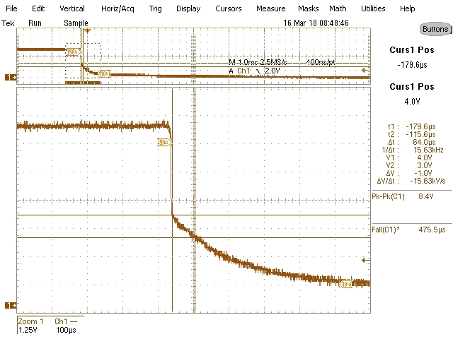
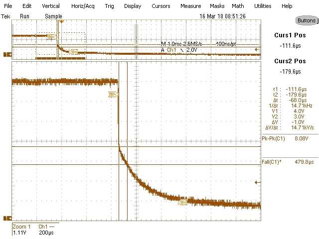
    I have verified that the PGA450-Q1 itself is not maintaining/holding any capacitive charge that would cause the VPWR ramp-down rate to be >=1V/ms. I used the PGA450-Q1EVM-S at a supply voltage of 8V to run this test instead of using the fullscale PGA450-Q1EVM to mitigate potential effects of supporting hardware components.

    Without any capacitance at VPWR and the power supply connected directly to VPWR, a mechanical disconnect of the supply itself yields a ramp-down of 64us from 4-3V (critical ramp-down region) at VPWR. When connecting the supply through the reverse battery protection diode (D2), there is no significant impact on the ramp-down rate without capacitance.

    Supply at VPWR: 

    Supply at EVM-S J2 connector:

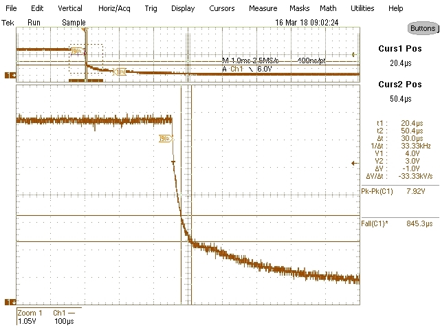
    With the supply still connected to J2 through the diode D2 to VPWR, I then added capacitance in parallel to the VPWR pin. Using standard decouple capacitor values of 0.01uF, 0.1uF, and 1uF, the maximum allowable capacitance was found to be <1uF to enable a 1V/1ms ramp-down on this setup:

    0.01uF at VPWR = 30us (GOOD)

    0.1uF at VPWR = 294us (GOOD)

    1uF at VPWR = 3ms (VIOLATION)

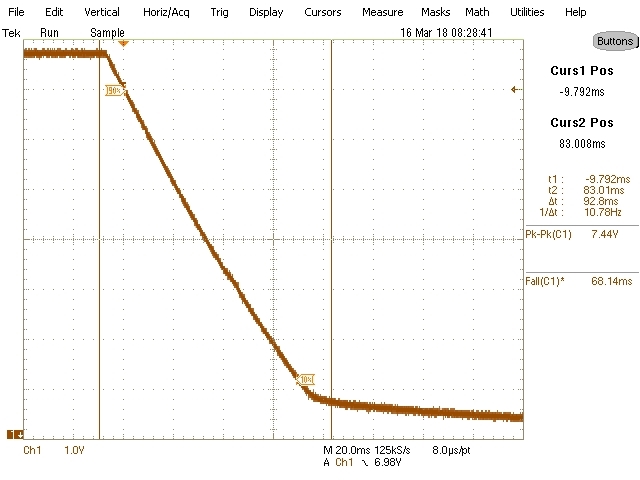
    A mechanical disconnect of the supply voltage was required because the bench supply itself has a slow-ramp down rate of 1V/12ms. Perhaps your high-side supply has a slow ramp-down rate in isolation. Here are two examples of the activity at VPWR when using the Output On/Off button feature of my power supply instead of physically disconnecting the supply (no difference at 4 to 3V ramp-down):

    VPWR when supply at VPWR (Cap 0.1uF)

    VPWR when supply at J2 connector through D2 (Cap 0.1uF)

    If you are unable to remove/reduce the 10uF capacitor at VPWR, or your itself supply is not at fault, then you can also consider adding a switch to float or ground the bleed-resistor. Effectively, you would need to use a GPIO (either from the PGA450 or external MCU) to drive/close a low-side nFET switch just prior to or simultaneously to shut-down of the pMOS so that the bleed resistor is not constantly sinking current during standard operation.

    I assume your pFET is switching fast enough to prevent a slow disconnect between your supply and PGA450-Q1. If not, this could also have an impact on the ramp-down rate.

  • Hi Akeem,

    Thank you very much for your efforts in this. I really appreciate the extra effort to help us here.

    I had suspected it was the capacitor on VPWR that is causing the slow ramp down.

    Our power source is from a 3.6V LiSOCl2 battery and TI's LM27313 Boost converter up to 7.5V.

    I have a PFET turning on and off the power to the converter, which is controlled by an RC circuit to slow down the turn on and a baker clamp to speed up the turn off. This ensures the input power is shut down very quickly. 

    I think I'll play around with the capacitor on VPWR and see if we can work with <1uF. It should be possible, but I need to test system stability for it.

    I'll post back what I find.

    Best regards,

    Mike