Other Parts Discussed in Thread: IWR1443, ENERGIA
Hi Everyone!
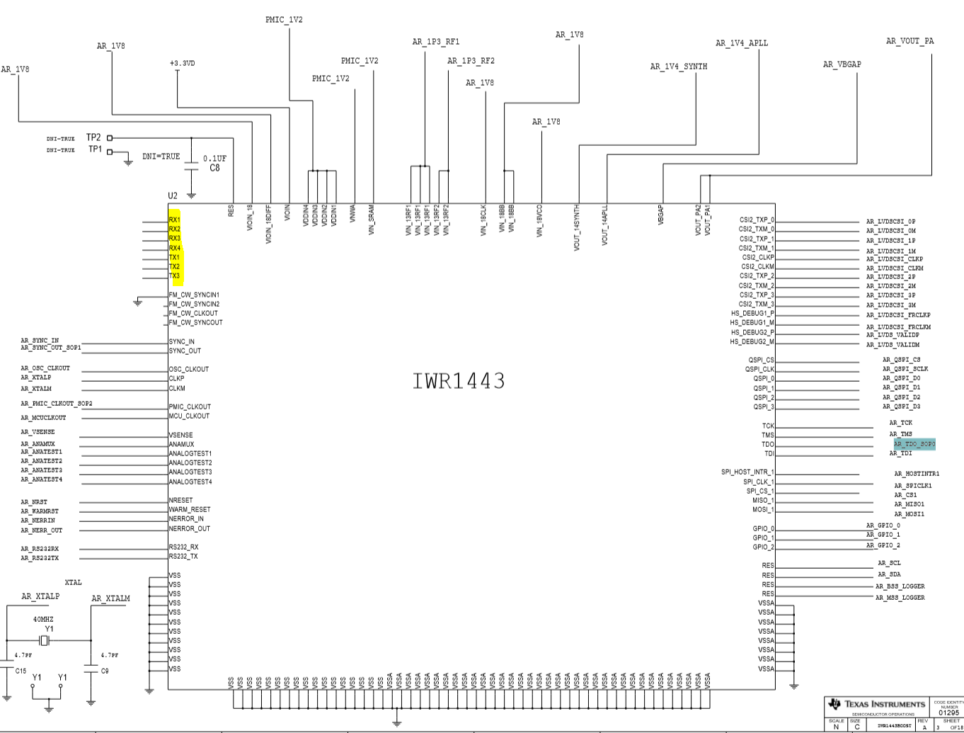
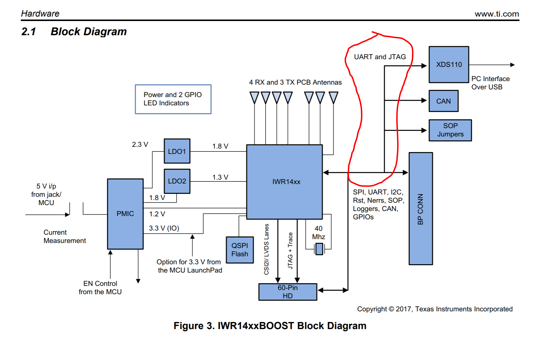
I have been playing around with the IWR1443 High Accuracy Lab and am successfully configuring the device using the CLI and reading the data via a Serial port emulator (CoolTerm). I have been able to change the output baud rate and recompile and still see the correct data. I am now at the point where I need to start integrating this thing into a telemetry project as the end goal is to get rid of the USB-Host (PC) and start interacting with the device directly via 3.3V - 5V Serial (Rx, Tx) or SPI. The end goal for me is to simply write an Energia sketch that would allow me to read the values streaming from the IWR1443 ( or maybe I should say from the XDS110?) as in the High_Accuracy_Lab but over UART rather than USB.
Can someone clarify and help me understand what type of communication is used between the IWR1443 and the XDS110 in this lab or in general for configuration and reading values?
Is the XDS110 merely a USB to UART Converter in this application eval module?
Can I replace the XDS110 with my own MCU and read streamed values from the IWR1443 and utilize the CLI commands over a Serial port? (Preferably the same Serial port before the Conversion to USB by the XDS110 so the code change is minimal or none at all.)
Sorry if there are some wrong assumptions in those questions but I would really appreciate any help in reading streamed values and writing configuration via CLI over a serial port and not USB.
Many Thanks!