This thread has been locked.

If you have a related question, please click the "Ask a related question" button in the top right corner. The newly created question will be automatically linked to this question.

FDC2212: Behavior of half sine wave on INA/INB

Part Number: FDC2212

Dear Technical Support Team,

Could you see attached file?

I have some problem and questions.

1.)

I see the left shift of top of half sine wave by depending on increasing IDRIVE.

Does the shortage of drive capability causes this behavior?

I guess that expected top should be center of half sine wave.

2.)

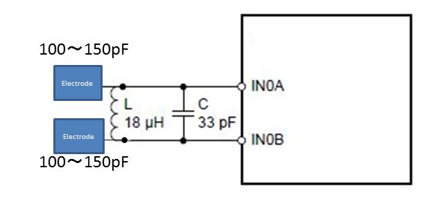
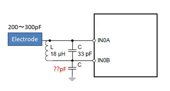
Unbalanced half sine wave between INA and INB.

Should I add more capacitor on INB to keep balance both?

The both half sine waves should be same behavior(the difference is just phase shift of 180 degree )

3.) 

To gain the altitude of sine wave, should I adjust the value of LC tank?

Current value:C=33pF、L=18uH

FDC.pdf

Best Regards,

ttd

  • Hi ttd,

    This is the result of having unbalanced sensor configuration. You could try to balance it by adding a capacitor to IN0B and GND or splitting the electrode in half and connecting on half to IN0A and the other to IN0B. To change the amplitude of the sine wave, you would adjust the Idrive setting. With an Idrive of 25 and 31, you are overdriving the signal to 2.17V and 2.9V, which is above the 1.8V max specified in the datasheet.

    Best,
    Jiashow
  • Hi Jiashow,

    Thank you for your reply.

     Does your comment "balance it by adding a capacitor to IN0B and GND" mean following figure?

    How size of capacitor(pF) should I try to add??

    Several dozen or hundred pF??

     Does your comment "splitting the electrode in half and connecting on half to IN0A and the other to IN0B" mean following figure?

    If I split in half size, does the amount of capacitor value be half?

    If I have a misunderstanding, could you make it correct?   

    Best Regards,

    ttd

  • Hi ttd,

    Yes, you are correct.

    For the first configuration, the C from IN0B to GND should be around the same value as your nominal electrode capacitance.
    For the second configuration, the electrodes capacitance should be halved.

    Best,
    Jiashow