This thread has been locked.

If you have a related question, please click the "Ask a related question" button in the top right corner. The newly created question will be automatically linked to this question.

IWR1642: Single tone frequency mode generate two peaks in Vector Network Analyzer

Part Number: IWR1642

Hello, 

We have designed our board using our own antenna using IWR1642 chip. In order to measure the parameters

of our antenna, we generated a single-tone frequency using capture demo (xwr16xx_capture_demo.bin ) in mmaeveSDK 1.1.0.2. 

Our configuration is shown below:

% ********************************************************************
% * Sample DEMO Script
% ********************************************************************
flushCfg
dfeDataOutputMode 2
channelCfg 2 1 0
adcCfg 2 2
adcbufCfg 0 0 1 1
lowPower 0 0
contModeCfg 80 0 0 6000 0 0 30 1 1024
setHSI LVDS ADC disable
sensorStart

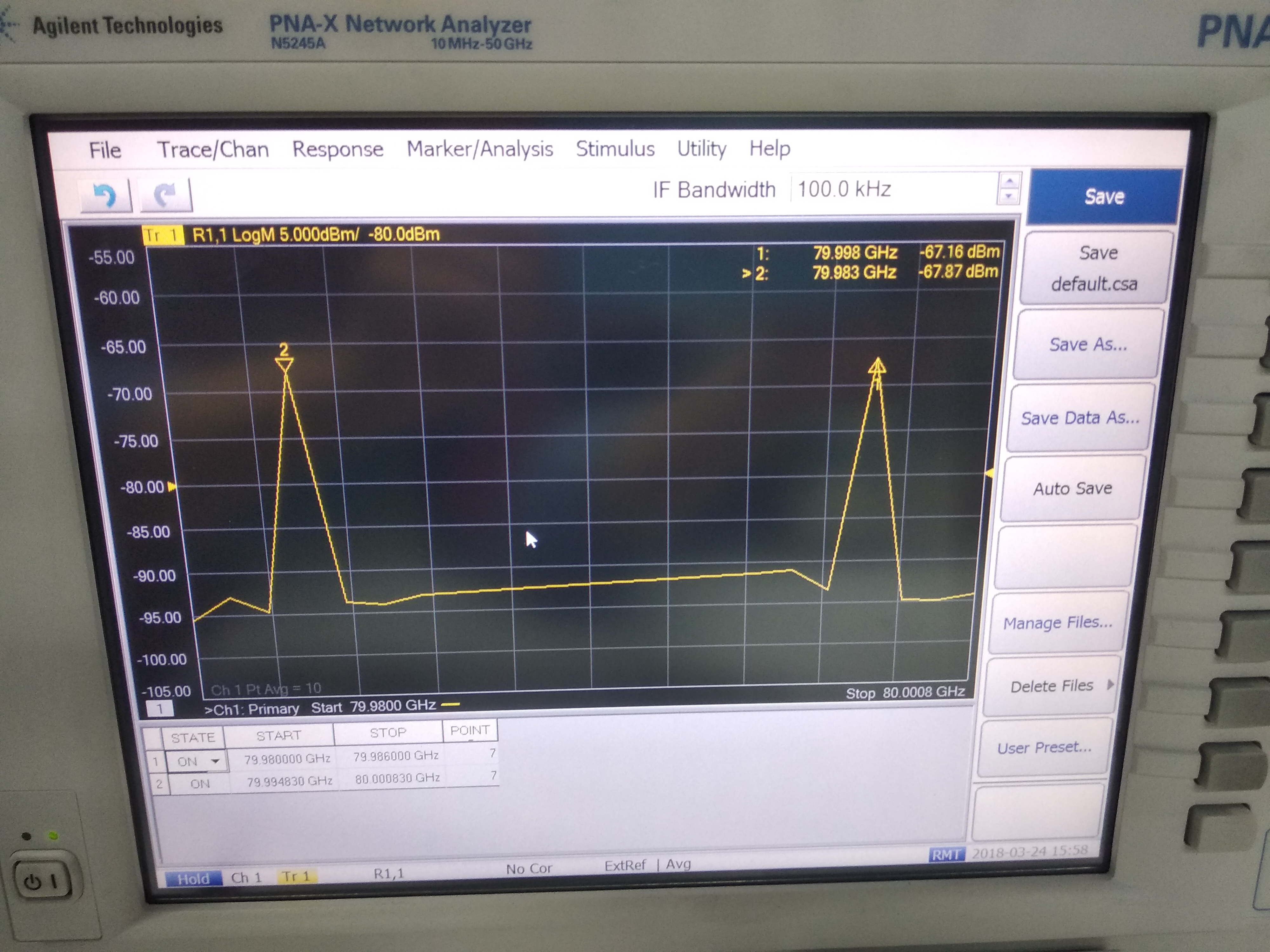
We used a small horn antenna to receive the signal from our antenna and down-converted it within 

50GHz ( the max we can measure with our VNA) . Under such configuration, we should received a single-tone

80GHz signal, however,  two peaks appeared as shown in the following pictures ( 79.983 and 79.998GHz):

I wonder whether something is wrong with my configuration?

Regards!

Tim


  • Hi Tim,

    This is an interesting question, I've asked an RF to look into this and someone should have an answer for you on Monday.


    Cheers,
    Akash
  • We have not seen this problem within in TI;

    Can we get more details on the LO and IF frequencies for the down-conversion?


    Typically we have seen these down-converter will have spurious tones which shows as spurs.

    Is there an instrument model number used for the down conversion process (to understand the specs/limitations of it).


    To Isolate, you could try with different frequency in continuous streaming mode to see if this goes away or not.


    Thanks and regards,

    CHETHAN KUMAR Y.B.


  • Hello, 

    The device under test is the radar which used IWR1642. The radar is tested in a anechoic chamber, which transmits single tone signal. The receiving path includes Receiving horn antenna->keysight 11970w(waveguide harmonic mixer, 75 to 110Ghz) ->keysight 85309B(LO/IF Distribution Unit)->N5245(PNA-X Microwave network analyzer). Actually the network analyzer is used as a spectrum analyzer here. The problem is when the radar transmits single tone signal, there are two signals displayed in the N5245 with almost the same amplitude, and the frequency spacing between the two signals is 15Mhz. We tried this for 78Ghz, 79Ghz, 80Ghz and 81 Ghz, similar phenomena are observed. So we are not sure if this is the configuration problem of the chip or the test system setup.   

  • Hello,

    Thanks for providing the setup details.

    It would be helpful to know what LO and IF frequency is associated with the 2 tones.
    Typically instrument sweeps the LO to keep a constant IF. Could you please provide information on what IF frequency it has been set to?

    You are using harmonic mixers which has higher conversion loss i.e 46dB, you need to ensure at the Spectrum(Network) Analyzer inputs you have sufficiently large power higher than the dynamic range of the analyzer. If you are using external LO driver, you need to ensure LO drivers are not emitting any spurious tones.

    Also you need to ensure RF power at the mixer input level sufficiently large within the dynamic range of the harmonic mixer (To ensure it's not picking any spurious tones). In past we have seen these harmonic-mixers emits lot of spurious tones which are not part Radar emission, to isolate that you could try changing LO frequencies and see if spurs moves away.

    By controlling device CW frequency and Mixer LO frequency independently you could isolate the problem w.r.t setup vs device.

    Thanks and regards,
    CHETHAN KUMAR Y.B.
  • We apologize that we were not able to provide you a timely answer.
    If this is still an issue we recommend that you start a new thread.