This thread has been locked.

If you have a related question, please click the "Ask a related question" button in the top right corner. The newly created question will be automatically linked to this question.

IWR1443: Radar Cube Memory

Part Number: IWR1443

Hello,

currently I am trying to define some chirp profiles and frames.

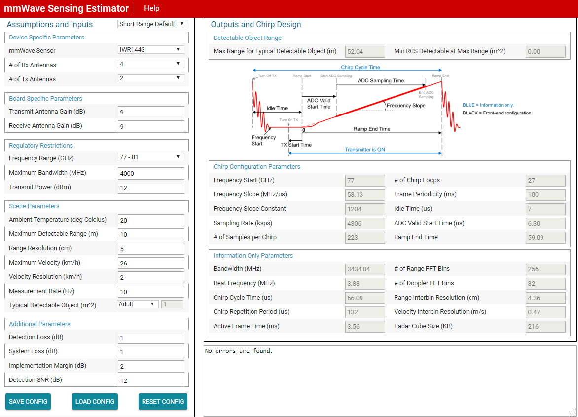
To get a first impression, I used the sensing estimator and tried to verify the calculated parameters.

I have some issues understanding the calculation for the Radar Cube Size.

For my understanding the Radar Cube Size should be calculated in the following way:

size = n_rx * n_tx * n_range_fft_bins * n_doppler_fft_bins * sampleSize

(where sampleSize is equal to 2*16 = 32 bit for complex sampling).

For the default settings (when starting the estimator) this is:

size = 4 * 2 * 256 * 32 * 32 = 2.097.152 bits

or size = 2.097.152 / 8 / 1024 = 256 KB (Kilobyte)

The size calculated by the estimator is 216 KB (see attached picture).

Where is my calculation wrong?

Thank you and best regards,

Enric

  • Hi Enric,

    I'm just guessing from looking at the numbers, but I think the number of doppler FFT bins being used for the Radar Cube Size computation is 27 instead of 32.

    Best Regards,
    Anand
  • Storage requirement depends on the implementation choices. If 2D output is not written back to radar cube, then the storage requirement will be 216 KB because you use the number of chirp loops, not number of doppler bins which is the next power of two of the chirp loops. If 2D is written back then it is 256 KB because you use the number of doppler bins. There are trade-offs in doing either way, not necessarily related to whether or not number of chirp loops is a power of 2, the trade-off are mostly MIPS (and memory if num chirp loops is not power of 2) and to some extent quality related. If 2D output is not written back to L3, then doppler FFT will have to be recomputed during angle processing although this computation (and the reading of the cube) is only required on the detected points (versus the entire cube write out of 2D) so it depends on max detected points allowed in an implementation. The trade-off analysis is further complicated by whether you write higher precision (e.g 24-bit or 32-bit) output of 2D or lower precision 16-bit output (same as 1D output to not expand the size) and also the fact that memory I/O and compute operate in parallel in the typical implementation so it depends on whether compute or I/O dominates. Such trade-offs have been discussed in Section 4 of for 16xx but they could be seen in a similar light for 14xx (a similar document for 14xx does not exist). For example, in the current out of box demo on 14xx, an option is provided to select lower (16-bit) or higher (24-bit) precision for 2D output, the former case does not require recompute of 2D FFT during but sacrifices quality whereas latter requires more MIPS during angle processing (latter method is the default), this is described in the oob demo's doxygen documentation in section "Data Path - Higher precision 2nd Dimension Processing"

  • Thank you for your answers, Anand and Piyush - especially for your detailed explaination, Piyush!

    This made it very clear and I think I understand everything. :)

    Thanks again,

    Enric