This thread has been locked.

If you have a related question, please click the "Ask a related question" button in the top right corner. The newly created question will be automatically linked to this question.

AWR1642: Modify the configurations of AWR1642 by using mmWave Sensing Estimator, but the sensor start fails !

Part Number: AWR1642

Hi,

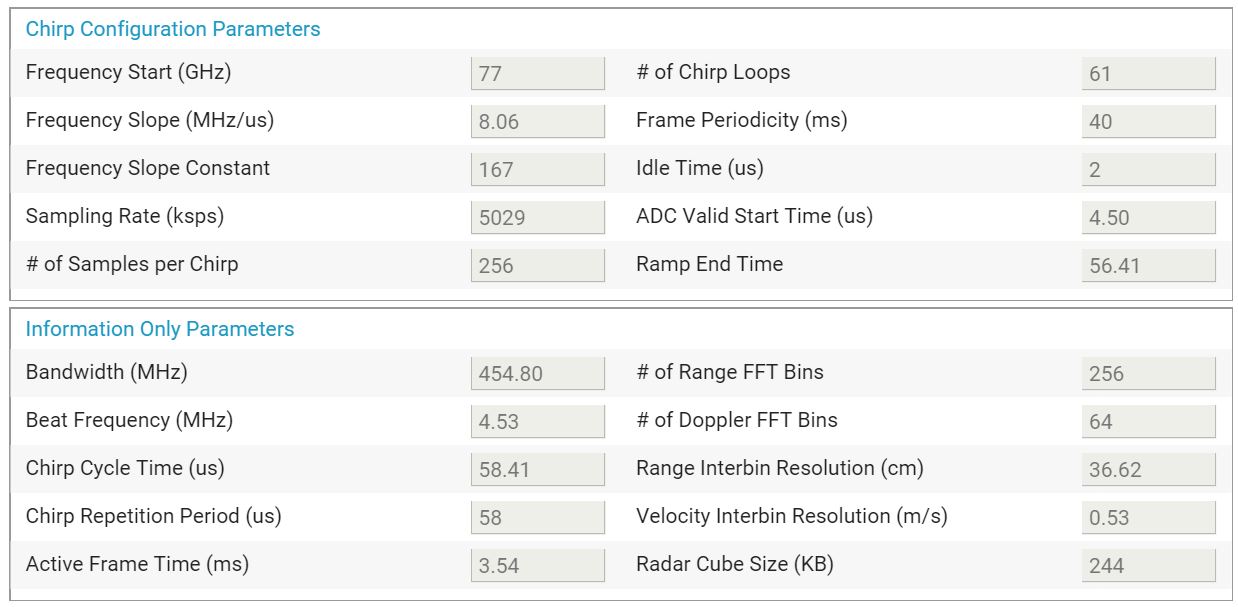
I would like to change numbers of TX from 2 to 1, and referring to the mmWave Sensing Estimator.

But sensor start fails.

My question is how to sensor start successfully by using TX=1 configuration?

Thanks.

-------------------------

Tx=2, sensor start successully, as follows:

-------------------------

sensorStop
flushCfg
dfeDataOutputMode 1
channelCfg 15 3 0
adcCfg 2 1
adcbufCfg -1 0 0 1 0
profileCfg 0 77 3 3 56 0 0  8 1 256 5000 0 0 30
chirpCfg 0 0 0 0 0 0 0 1
chirpCfg 1 1 0 0 0 0 0 2
bpmCfg -1 0 0 1
frameCfg 0 1 64 0 100 1 0
lowPower 0 0
guiMonitor -1 1 0 0 0 0 0
cfarCfg -1 0 0 8 4 4 0 6000
cfarCfg -1 1 0 8 4 4 0 6000
peakGrouping -1 1 1 1 1 224
multiObjBeamForming -1 0 0.5
calibDcRangeSig -1 0 -5 8 256
extendedMaxVelocity -1 1
clutterRemoval -1 0
compRangeBiasAndRxChanPhase 0.0 1 0 1 0 1 0 1 0 1 0 1 0 1 0 1 0
measureRangeBiasAndRxChanPhase 0 1.5 0.2
nearFieldCfg -1 0 0 0
CQRxSatMonitor 0 3 5 127 0
CQSigImgMonitor 0 127 4
analogMonitor 1 1
lvdsStreamCfg -1 0 0 0
sensorStart

-------------------------

-------------------------

Tx=1, sensor start fail, as follows:

-------------------------

sensorStop
flushCfg
dfeDataOutputMode 1
channelCfg 15 1 0
adcCfg 2 1
adcbufCfg -1 0 0 1 0
profileCfg 0 77 2 4.5 556.41 0 0  8.06 1 256 5029 0 0 30
chirpCfg 0 0 0 0 0 0 0 1
bpmCfg -1 0 0 1
frameCfg 0 1 64 0 100 1 0
lowPower 0 0
guiMonitor -1 1 0 0 0 0 0
cfarCfg -1 0 0 8 4 4 0 6000
cfarCfg -1 1 0 8 4 4 0 6000
peakGrouping -1 1 1 1 1 224
multiObjBeamForming -1 0 0.5
calibDcRangeSig -1 0 -5 8 256
extendedMaxVelocity -1 1
clutterRemoval -1 0
compRangeBiasAndRxChanPhase 0.0 1 0 1 0 1 0 1 0 1 0 1 0 1 0 1 0
measureRangeBiasAndRxChanPhase 0 1.5 0.2
nearFieldCfg -1 0 0 0
CQRxSatMonitor 0 3 5 127 0
CQSigImgMonitor 0 127 4
analogMonitor 0 0
lvdsStreamCfg -1 0 0 0
sensorStart

-------------------------

=================

mmWaveSDK 1.2.0.5

=================

  • Kris,

    Based on the profile cfg files you provided, I have extracted them below for easy analysis.

    profileCfg           

    Profile ID: 0

    Start Frequency: 77

    Idle Time: 2

    ADC Start Time: 4.5

    Ramp End Time: 556.41

    TX Output Power: 0

    TX Phase Shifter: 0 

    Frequency Slope Constant:  8.06

    TX Start Time: 1

    Number of ADC Samples: 256

    ADC Sampling Rate: 5029

    HPF1 Frequency: 0 (175 KHz)

    HPF2 Frequency: 0 (350 KHz)

    RX Gain: 30

    Based on the Frequency Slope Constant and the Ramp Idle time specified in your configuration, the bandwidth of your profile would be 4.485 GHz, which outside the maximum allowed bandwidth. Using the 77-81 GHz band, the maximum bandwidth for any profile is 4 GHz. Please update your configuration so that it less than 4 GHz.

    Please reply if you have any additional questions.

    Regards,

    Kyle

  • Hi Kyle,

    Thanks for your reply.

    I moified the "Ramp End Time" from 556.41 to 56.41

    The sensorStart still fails.

    Is there any detail configuration I missed ? 

    Thanks.

    ------------------------------------

    sensorStop
    flushCfg
    dfeDataOutputMode 1
    channelCfg 15 1 0
    adcCfg 2 1
    adcbufCfg -1 0 0 1 0
    profileCfg 0 77 2 4.5 56.41 0 0  8.06 1 256 5029 0 0 30
    chirpCfg 0 0 0 0 0 0 0 1
    bpmCfg -1 0 0 1
    frameCfg 0 1 64 0 100 1 0
    lowPower 0 0
    guiMonitor -1 1 0 0 0 0 0
    cfarCfg -1 0 0 8 4 4 0 6000
    cfarCfg -1 1 0 8 4 4 0 6000
    peakGrouping -1 1 1 1 1 224
    multiObjBeamForming -1 0 0.5
    calibDcRangeSig -1 0 -5 8 256
    extendedMaxVelocity -1 1
    clutterRemoval -1 0
    compRangeBiasAndRxChanPhase 0.0 1 0 1 0 1 0 1 0 1 0 1 0 1 0 1 0
    measureRangeBiasAndRxChanPhase 0 1.5 0.2
    nearFieldCfg -1 0 0 0
    CQRxSatMonitor 0 3 5 127 0
    CQSigImgMonitor 0 127 4
    analogMonitor 0 0
    lvdsStreamCfg -1 0 0 0
    sensorStart

    ------------------------------------

  • Kris,

    It looks like there are a couple of issues at play here.

    The first issue relates to your chirp configuration. You need to increase the idle time to at least 3 us or higher. The current idle time does not allow enough DFE spill time. There needs to be enough time between chirps for the VCO to ramp down and settle before sending out another chirp.

    The second issue relates to your frameCfg command. The first two arguments in the frameCfg command specify the start chirp and end chirp for your frame. However, in your current configuration, you only create a single chirp designated to profile 0. Therefore, you cannot specify an end chirp of 1 as you do in your configuration as you have not defined a chirp for profile 1. Either create a second chirp for profile 1 or change the arguments so the start and end chirp are both set to 0.

    Regards,
    Kyle

  • Kris,

    After some further analysis, I have come up with the following set of CLI commands for the chirp and frame configuration you are going for:

    sensorStop
    flushCfg
    dfeDataOutputMode 1
    channelCfg 15 1 0
    adcCfg 2 1
    adcbufCfg -1 0 0 1 0
    profileCfg 0 77 2 4 56.4 0 0 8.06 0 256 5029 0 0 30
    chirpCfg 0 0 0 0 0 0 0 1
    bpmCfg -1 0 0 1
    frameCfg 0 0 64 0 100 1 0
    lowPower 0 0
    guiMonitor -1 1 0 0 0 0 0
    cfarCfg -1 0 0 8 4 4 0 6000
    cfarCfg -1 1 0 8 4 4 0 6000
    peakGrouping -1 1 1 1 1 224
    multiObjBeamForming -1 0 0.5
    calibDcRangeSig -1 0 -5 8 256
    extendedMaxVelocity -1 1
    clutterRemoval -1 0
    compRangeBiasAndRxChanPhase 0.0 1 0 1 0 1 0 1 0 1 0 1 0 1 0 1 0
    measureRangeBiasAndRxChanPhase 0 1.5 0.2
    nearFieldCfg -1 0 0 0
    CQRxSatMonitor 0 3 5 127 0
    CQSigImgMonitor 0 127 4
    analogMonitor 0 0
    lvdsStreamCfg -1 0 0 0
    sensorStart

    Using these CLI commands, now the only issue that is raised is from the DSS. Specifically, the exception raised is "Extended maximum velocity technique is supported only in TDM MIMO." This exception is raised because only a single chirp is defined. A second chirp would need to be defined while enabling a different TX transmitter than the first chirp.

    Regards,
    Kyle
  • Kris,

    Here is a set of CLI commands that should work and address the TDM MIMO issue raised in my previous post. Please let me know if you have any questions. These commands have been verified on AWR1642 using SDK v1.2

    sensorStop
    flushCfg
    dfeDataOutputMode 1
    channelCfg 15 3 0
    adcCfg 2 1
    adcbufCfg -1 0 0 1 0
    profileCfg 0 77 2 4 56.4 0 0 8.06 0 256 5029 0 0 30
    chirpCfg 0 0 0 0 0 0 0 1
    chirpCfg 1 1 0 0 0 0 0 2
    bpmCfg -1 0 0 1
    frameCfg 0 1 64 0 100 1 0
    lowPower 0 0
    guiMonitor -1 1 0 0 0 0 0
    cfarCfg -1 0 0 8 4 4 0 6000
    cfarCfg -1 1 0 8 4 4 0 6000
    peakGrouping -1 1 1 1 1 224
    multiObjBeamForming -1 0 0.5
    calibDcRangeSig -1 0 -5 8 256
    extendedMaxVelocity -1 1
    clutterRemoval -1 0
    compRangeBiasAndRxChanPhase 0.0 1 0 1 0 1 0 1 0 1 0 1 0 1 0 1 0
    measureRangeBiasAndRxChanPhase 0 1.5 0.2
    nearFieldCfg -1 0 0 0
    CQRxSatMonitor 0 3 5 127 0
    CQSigImgMonitor 0 127 4
    analogMonitor 0 0
    lvdsStreamCfg -1 0 0 0
    sensorStart

    Regards,
    Kyle
  • And if you're looking to only use a single TX, then this set of CLI commands would work:

    sensorStop
    flushCfg
    dfeDataOutputMode 1
    channelCfg 15 1 0
    adcCfg 2 1
    adcbufCfg -1 0 0 1 0
    profileCfg 0 77 2 4 56.4 0 0 8.06 0 256 5029 0 0 30
    chirpCfg 0 0 0 0 0 0 0 1
    bpmCfg -1 0 0 1
    frameCfg 0 0 64 0 100 1 0
    lowPower 0 0
    guiMonitor -1 1 0 0 0 0 0
    cfarCfg -1 0 0 8 4 4 0 6000
    cfarCfg -1 1 0 8 4 4 0 6000
    peakGrouping -1 1 1 1 1 224
    multiObjBeamForming -1 0 0.5
    calibDcRangeSig -1 0 -5 8 256
    extendedMaxVelocity -1 0
    clutterRemoval -1 0
    compRangeBiasAndRxChanPhase 0.0 1 0 1 0 1 0 1 0 1 0 1 0 1 0 1 0
    measureRangeBiasAndRxChanPhase 0 1.5 0.2
    nearFieldCfg -1 0 0 0
    CQRxSatMonitor 0 3 5 127 0
    CQSigImgMonitor 0 127 4
    analogMonitor 0 0
    lvdsStreamCfg -1 0 0 0
    sensorStart

    Regards,
    Kyle
  • Hi Kyle,

    Thanks for your reply.

    I also just found this situation, but I don't know why at that moment.

    After your explanation, I understand that "extendedMaxVelocity" is how to use.

    Thank you very much for helping out.