This thread has been locked.

If you have a related question, please click the "Ask a related question" button in the top right corner. The newly created question will be automatically linked to this question.

mmWave Sensors: PLL locked RF signals

Other Parts Discussed in Thread: IWR1443

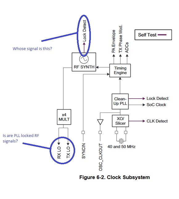
Hello everyone. I have a question.

Is the output frequency (RX LO, TX LO) of the AWR or IWR modules locked by the PLL?

I attach a picture from the datasheet to IWR1443 explaining the question.

Thanks.

  • Hello,

    Thank you for your interest in TI mmWave sensors. Inside the device we have a single synthesizer, the RX LO and TX LO shown in the diagram are the RX LO distribution and TX LO distribution network and not Local oscillators. Sorry for the inconvenience caused due to this.

    Thanks and Regards,
    CHETHAN KUMAR Y.B.
  • Thanks for your reply. What you say is understandable. But nevertheless,what function is performed by PLL within the RF module? Is captured output radio frequency or not?

    P.S. Sorry for my english.
  • Hello,

    PLL takes the input from the 40MHz crystal oscillator, it acts as a jitter clean up circuit and provides improved phase noise clock as a reference input to RF synthesizer which generates FMCW chirps based on the inputs from the timing engine. After frequency multiplication (by factor of 4) these signals would be fed to Receiver and Transmitter LO distributor.

    For the Transmitter, output of LO distributor goes into on-chip power amplifier and from there to Antenna ports. For Receiver from the Low noise amplifier signal goes into Mixer and Mixer gets Receiver LO distributor signal to generate IF signals.

    I hope above explanations clarifies your doubts.

    Thanks and regards,
    CHETHAN KUMAR Y.B.