This thread has been locked.

If you have a related question, please click the "Ask a related question" button in the top right corner. The newly created question will be automatically linked to this question.

LDC2114: Distance between IN lines and other Signals

Part Number: LDC2114

Hello,

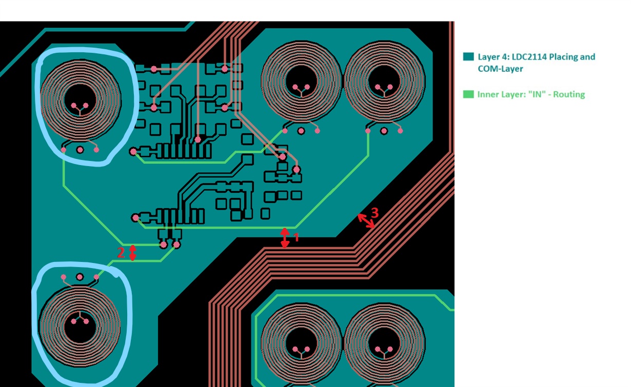
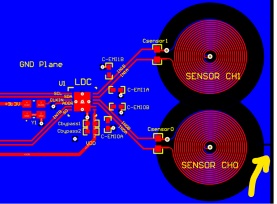
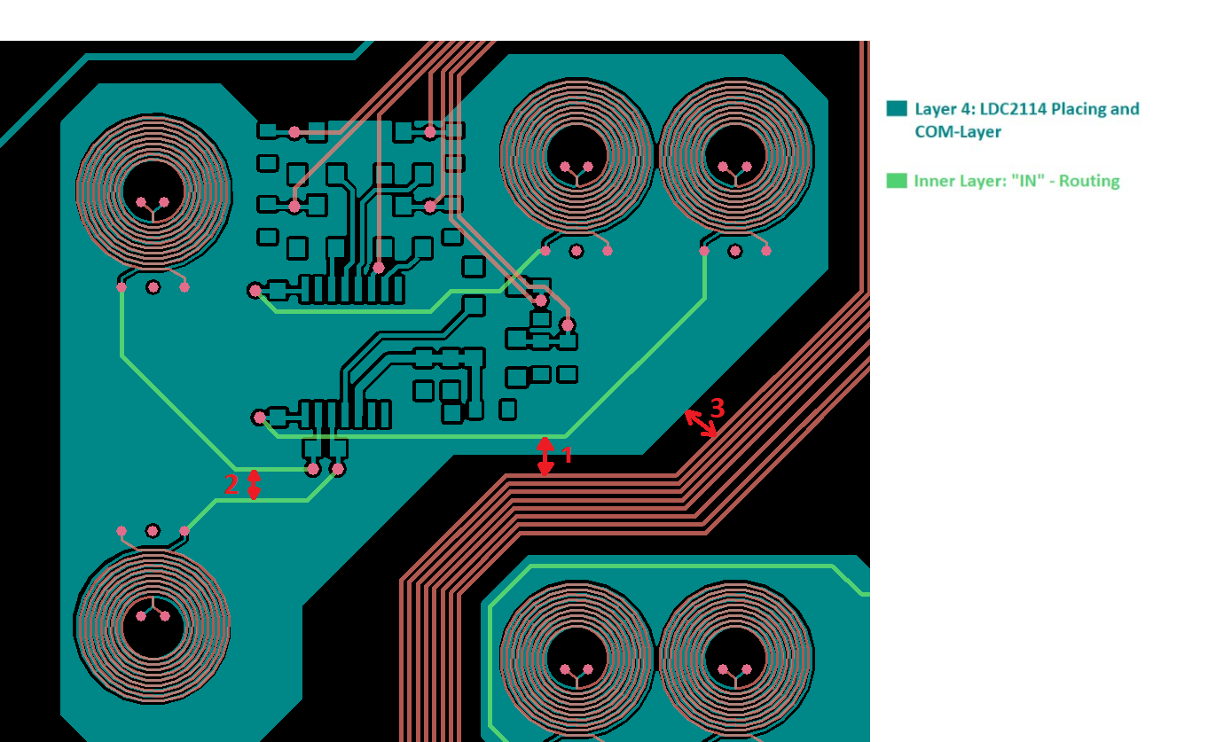
implementing LDC2114 we have some quesion about routing distances, please see the picture below:

1.) What should be the minimal distance between IN-traces and other signals (GPIO, I2C, Power etc)

2.) What should be the minimal distance between IN-traces and other IN-traces?

3.) What should be the minimal distance between COM-plane and other signals(GPIO, I2C, Power etc)

Thank you very much and kind regards,

Clemens

  • Hi Clemens,

    The IN traces are time-domain multiplexed, so the only routing consideration you would need to take into account is capacitance with other traces. All of the IN, I2C, Power, and GPIO traces look fine.

    Overall, the layout near the coils is the most important. There are a couple of changes to your COM plane that you should make. First, there should not be any closed loops of conductive materials near the coils. If there are, eddy currents can form here that will attenuate the coil's magnetic field. A cut should be placed in any conductive closed loops around the coils to avoid this. Second, you should keep copper away from the edges of the coil - minimize any conductors within at least 30% of the coil's diameter. I've attached an example layout showing both the recessed copper and a cut around the coils.

    Regards,

  • Hi Kristin,

    thank you very much for your answer.

    We will take your advices into account,but we're not quite sure what you mean with "conductive closed loops around the coils" and the cut.

    Could you explain that particularly or show some more examples?

    Kind regards,

    Clemens

  • Hi Clemens,

    I've drawn on the picture of your layout in light blue to show examples of the closed loops. Essentially, you have an uninterrupted conductive path around your coils, and eddy currents can flow here. They will flow in concentric circles around your coils and oppose their magnetic fields,which would decrease their effective inductance. Recessing the copper away from the coils' circumferences can help, as can breaking the conductive path (with a cut). I've also modified the picture I sent you previously with a yellow arrow to show the small gap in the copper surrounding the bottom coil, which is what we refer to as a cut. Although I've only circled two of your coils, you should recess the copper and make cuts around all of them.

    Regards,