This thread has been locked.

If you have a related question, please click the "Ask a related question" button in the top right corner. The newly created question will be automatically linked to this question.

LDC1312: LDC1312

Part Number: LDC1312
Other Parts Discussed in Thread: LDC1612

Hello Everyone,

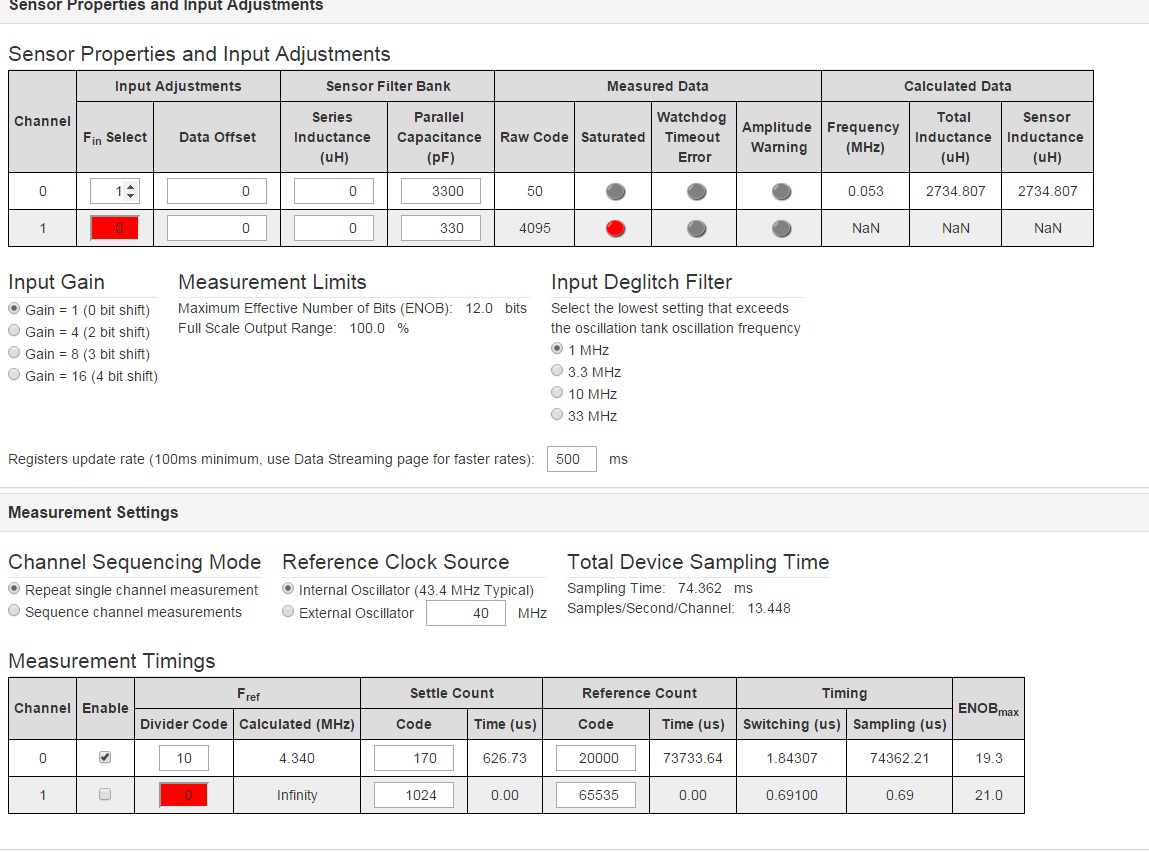
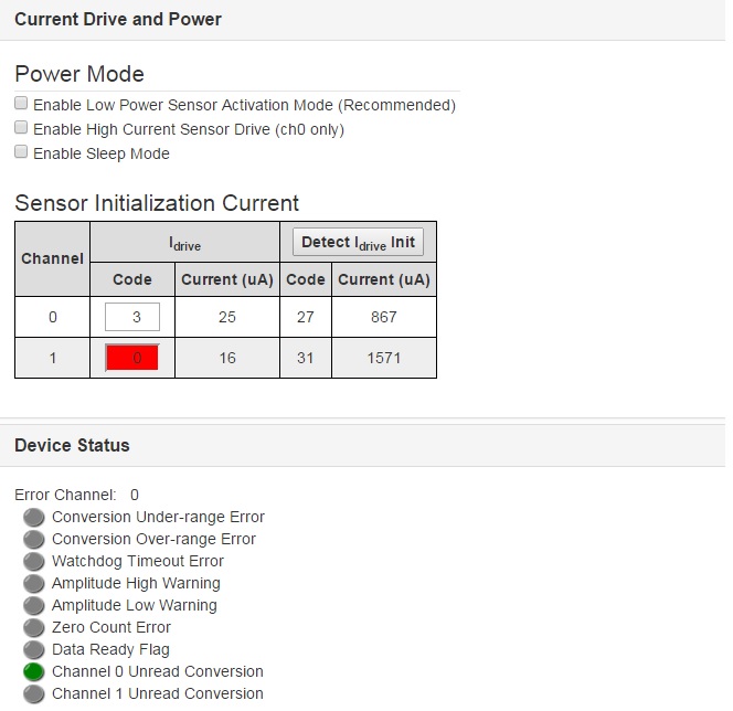
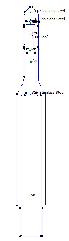
I have and inductor with L = 2,2mH and the capacitor to create the oscilation frequency is C = 3,3nF. The oscilation frequency is about 58000 KHz. I´m using the LDC1312 to get the presence of the target. When I place the target around the inductor, instead of, the frequency increase ie is decreasing. Ii this an abnormal behavior in lower frequencies? The configuration in Sensing Solutions EVM GUI is:

  • Hi Filipe,

    Based on your problem description I'm not quite sure if the sensor frequency is increasing or decreasing when you bring the target near to it. If the frequency is increasing, this is normal behavior for the sensor. If the frequency is decreasing, this may be because your target is ferrous. In this case, the magnetic field lines from the inductor would permeate through the target, which would increase the sensor's inductance and decrease the sensor frequency. If you cannot change your target material, operating at a frequency greater than 1 MHz could mitigate the target's permeability. See the LDC Target Design App Note for more details on target material and shape. 

    Regards,

  • Hello Kristin,

    Thank you very much for your support.

    I have understood your comments and suggestions. According that document you ask to read, in Steel and Magnetic Material Targets, the sensor frequency < 20 KHz or sensor frequency > 1MHz. In my case the best solution is the first condition. Actually the sensor frequency is around 57 KHz. I will try to reduce that frequency and make a test. 

    Another question: Do you an ideia to measure the Signal/Noise ratio using the LDC1312?

    Thank you very much

  • Hi Filipe,

    Using a sensor frequency below 20 kHz will reverse the expected effects of bringing the target near the coil. Instead of the target reducing the inductance as it approaches the coil, it will increase the inductance and decrease the sensor frequency. This is the effect of the AC magnetic field on the ferrous target. Note that measuring the inductance this way is very sensitive to temperature change and part-to-part variation. Though the LDC1312 can be used to measure inductance increases instead of inductance decreases, taking advantage of the target's skin effect at higher frequencies generally produces more consistent measurements. 

    May I ask why your sensor frequency needs to be so low? You will likely experience decreased resolution with the LDC1312 for sensor frequencies below 100 kHz. You could use the LDC1612 to combat this, which has the same pinout as the LDC1312, but has 28 bits of resolution instead of 16. You could also continue using the LDC1312 with a higher sensor frequency, which can be achieved by lowering the values of your inductor and capacitor. The inductance has no affect on the sensing range; only the diameter of the sensor coil determines the sensing range. 

    To determine the SNR of your sensor, first measure the code change of the sensor when no target is present. Determine the standard deviation of the code change and use +/- 3 standard deviations from the mean as your peak-to-peak noise value. Then repeat the process with the target at the maximum desired detectable distance (the response will be the weakest at this distance) to determine your peak-to-peak signal value. Use the rms values of both to determine your SNR. 

    Regards,

  • Hello Kristin,

    Thank you very much for your support again.

    I need a lower sensor frequency because in my application I have a coil (ferrite + wire) and this coil is placed in a housing built of Stainless steel. The magnetic field generated by the coil should pass this "fence" and detect the target. The sensor Works like a steel face inductive sensor. A drawing showing my application you can see in the Picture below:

    Look, the sensor frequency should be lower as possible to detect the target.

    The SNR you mentioned in previous e-mail could be calculate in the following way:


    The mathematical formula above is to calculate de rms value.


     The final result should be <1.

    When you mention "code change", Is it the same raw code? Or it can be frequency or inductance?

    Thank you very much for your support

  • Hi Filipe,

    I'm glad to see you are using FEMM to simulate your coil. I would suggest adding a target to your simulation to determine whether or not your coil's inductance will change within the steel housing. If you have difficulty with this you can send your FEMM files to me via a private message.

    Unfortunately, I am unable to view the pictures you attached of the SNR calculations. Could you try reattaching them? When I mention code change, I do mean the raw code output by the device. I would recommend using this to calculate SNR instead of inductance or frequency. This will yield a more accurate SNR than inductance or frequency, which are calculated in the GUI based on the raw code.

    Regards,
  • Hello Kristin,

    Thank you very much for your support and help.

    The mathematical formulas are attached again:

    The first one is the RMS value from de signal. The signal means the coil with target.

    The second is the RMS value from the noise. The noise means the coil without target.

    The SNR should be < 1.

    I have tried to write a private message containing the FEMM files, but I could not find. Please, could you show the way?

    Thank you very much

    Best Regards

  • Hi Filipe,

    Your RMS noise formula is correct. I want to clarify that your RMS signal value must include the full raw code values of your signal, not just the noise at the signal level. If you do not include the full raw code values of the signal, you will need to compensate for this in your SNR calculation. You would need to find the difference between the means of the noise at the noise floor and at the signal level (delta), then divide by the RMS value of the noise floor. Your formula would become: 

    SNR = delta/Xnoise

    This will make the SNR much higher than 1, which is necessary to discern the signal from the noise. I would recommend an SNR of at least 10 (or 20dB). This is so the SNR is still in a viable range when the system is used outside of perfect lab conditions.

    I have sent you a private message, so you should be able to reply to that with your FEMM files.

    Regards,

  • Hello Kristin,

    I have the following to illustrate my idea:

    I have a vector with the raw code received from my measured without target. I got the standard deviation and the results was on value, like X. I got the mean from this same vector and the value was, like Y.

    I made the same process with target and I got X' and Y'.

    In this case DELTA means: X' - X

    and SNR = (X' - X)/Xnoise;

    where X' = median of signal with target

              X = median of the signal whitout target (noise)

    What do you think?

    Best Regards 

    Thank you very much

  • Hi Filipe,

    It should be SNR = (Y' - Y)/Xnoise, where Y' is the mean of the signal with the target, Y is the mean of the noise floor, and Xnoise is the RMS value of the noise floor.

    Regards,