This thread has been locked.

If you have a related question, please click the "Ask a related question" button in the top right corner. The newly created question will be automatically linked to this question.

LDC1614EVM: Sensor Distance to LDC / Verification

Part Number: LDC1614EVM
Other Parts Discussed in Thread: LDC1614,

Hi,

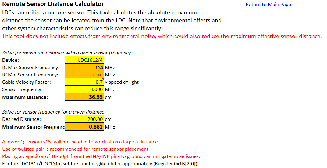
I have an application that requires sensors to be as far as 2m. I’m experiencing sensor drop out and saturation issues, but not sure if this may be the cause.

Note I'm not talking about the distance of the Target to the sensor.

Does anyone have any recommendation for this situation?

LDC to Sensor distance: 1.6m away, (Cp is next to LDC to account for the additional L added by connecting wire)

Sensor:

Diameter: 13.9mm

Turns/Layer: 19

Layers: 2

Trace/Spacing: 0.15mm/0.15mm

Target Square: 4xSensor Diameter, Stainless Steel, Axial Motion, Max/Min Distance 5mm/0.25mm

 The connecting cable is 2 wire, (AWG32), twisted pair with shield and drain. (drain grounded)

When sensors are next to LDC, Inductance measures 8.3uH @ 3.03MHz, @ 1.6m - 14.2uH @ 2.9MHz

  • Hello,

    Can you clarify what is meant by dropping out and saturation? Have you already checked the IDRIVE setting and sensor amplitude? It will be helpful to get an oscilloscope capture of sensor waveform at the inductor as well as near the device. 

    Also note that driving an LC tank with a long connection is typically not recommended. If the length of the wire gets long (in comparison to the sensor wavelength) then you could run into transmission line effects like phase shifts that can corrupt the switching behavior of the device. If your sensor frequency is 3MHz then we don't recommend a transmission length >0.35m. If you have to drive the sensor remotely at 2m distance then you should consider lowering your sensor frequency <1MHz to avoid this effects.

    Just use caution when lowering the sensor frequency, because if the inductor is fixed then increasing the sensor capacitor will lower the frequency but also lower the sensor RP and Q factor. If the RP gets too low then the sensor amplitude will be low as a result or the device may not be able to drive the sensor. If this is a single channel application then you can use Channel 0 and High Current Drive mode to increase the the capabilities of the device.

    Regards,

    Luke LaPointe

  • Thank you Luke,

    I think I will have to split my board and make the I2C the long run between sensors. My project needs four (LDC1614) and could grow as much as eight.

    Could you point me in the direction of a firmware forum, (LDC1614EVM firmware provided), I have some basic taskScheduler questions, I have not found anything related to my issues in the general forums and there seems to be little support on this area other than just offering the software.

    Regards,

    Edgar.

  • Hi Edgar,
    Thanks for the confirmation! For source code examples for the LDC1614EVM, we've included some with in the FAQ ( e2e.ti.com/.../295036 ) as well as an example project when you download the Sensing Solutions GUI ( www.ti.com/.../snoc028 ):
    The code source included with the GUI can be found in the following directory: C:\ti\Sensing Solutions EVM GUI-1.9.4\EVM Firmware\FDC2x14_LDC13xxRevB_LDC16xxRevB_EVM_Firmware_source
    For specific questions about how the MSP430 functions, I'd recommend posting a question on that forum:
    e2e.ti.com/.../
    Regards,
    Luke