This thread has been locked.

If you have a related question, please click the "Ask a related question" button in the top right corner. The newly created question will be automatically linked to this question.

AWR1642BOOST: mmwave sensor in AWR1642BOOST EVM did not respond

Part Number: AWR1642BOOST
Other Parts Discussed in Thread: AWR1642, UNIFLASH

I got a new AWR1642BOOST EVM for autonomous driving application. But i'm not able to implement any demo on it. Even when i tried to visualize the point cloud data through ROS package, it's giveing an error saying that "mmwave sensor did not respond with 'Done' ". Is there an issue with the hardware? If so please tell me the possible solution at the earliest possible. Also if it's 
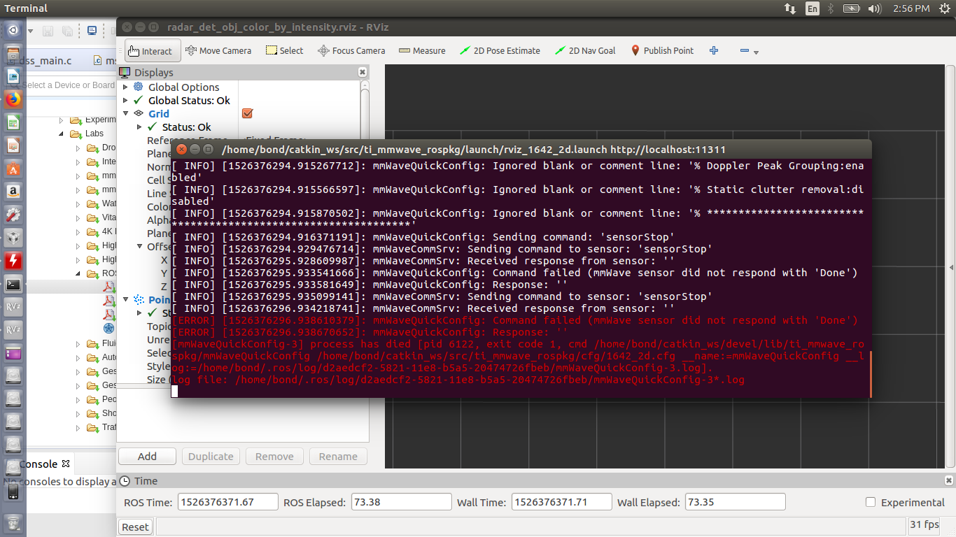
not a hardware issue please help me further with this.

Thanks

Regards

  • Hello Rahul,

    Does your new AWR1642BOOST EVM have a sticker on it that says "ES2.0"? If so, then it will not work with the ROS Point Cloud Visualizer lab v1.3 that is part of the Industrial Toolbox version 2.3.1. The new ES2.0 devices require mmWave SDK version 2.0 that was recently released. Several 1642 labs have been ported to support mmWave SDK 2.0, but not all yet. You can see which labs support the new SDK and ES2.0 EVM by looking at the Labs overview page in the Industrial Toolbox on the TI Resource Explorer at the following link.

    dev.ti.com/.../

    (The ROS Point Cloud Visualizer lab specifically will most likely require an updated chirp profile config file to work with the out-of-box (mmw) demo from mmWave SDK 2.0 for AWR1642 ES2.0 EVMs.)

    In order to verify that your hardware is working, I would recommend flashing the mmWave SDK out-of-box (mmw) demo on the EVM and trying it out with the mmWave Demo Visualizer. The instructions to flash the EVM and run the mmw demo are in the mmWave SDK user guide. If you have an ES2.0 EVM then you will need mmWave SDK version 2.0. If the EVM does not have an ES2.0 sticker then it should be the older ES1.0 EVM and you would need to use mmWave SDK version 1.2.

    Link to mmWave SDK:
    www.ti.com/.../MMWAVE-SDK

    Please also verify that you are using a power supply that can supply at least 2.5 Amps at 5V and that you are using the USB cable that came with the EVM to connect the EVM directly to the PC (longer cables or adding a USB extension cable can cause issues).

    Please mark the thread as answered if your issue is resolved or reply with more information if more support is required.

    Regards,
    John
  • sir,
    There is no such sticker in the EVM. I think it's a older version. I tried to flash the out of box demo on the evm, i was successfully able to upload the '.bin' file using the Uniflash too, but when i try to use the Demo Visualizer, i am able to detect the ports but it gets stuck showing the message ' waiting for data... '. I waited for more than 30 mins but still the same message and there was nothing in the console. I think the RF end is not responding.

    I'm using an external power supply at 5V but the evm is just drawing a current of 0.34 A from the supply. Kindly help.
  • After you configure the ports in the Demo Visualizer and it says "waiting for data..." at the bottom you will also need to press the "SEND CONFIG TO MMWAVE DEVICE" button at the bottom of the GUI to send the config and start the mmWave device measurements. when you click the button, you should see the UART commands and responses scroll by in the "Console Messages" window. Can you send the output from the Console Messages window?

    Also, the device draws a smaller current before it starts performing Radar measurement, but it will draw more current once the sensorStart command at the end of the config is issued. Therefore, it is important to verify that the external power supply can supply at least 2.5 Amps.

    Regards,
    John
  • Thank you, sir. I think the issue was casuse of, that i uploaded the demo from a different version of SDK.