Other Parts Discussed in Thread: AFE5808A
We have been trying out the AFE5818 using the eval board and we have run into an issue. When we apply a slope to VCNTL, we see that there are non-linearities at lower gains. The steeper the slope, the worst the error is. Here is what we did:
- We changed C201 to C202 on the Eval Board to 100pF.
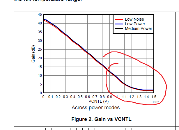
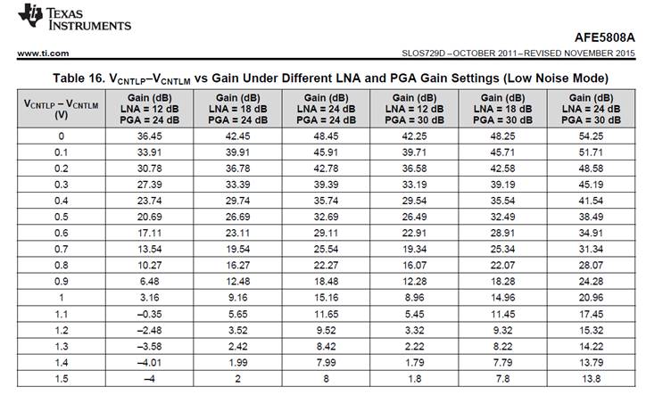
- We statically measured the voltage required on VCNTLP to get a specific gain in 1 dB steps in order to build a VCNTL vs gain curve with a 38 dB range. We drive the AFE5818 gain control in signal ended mode.
- We use this curve and apply it using a function generator at a specific slope (for example 5dB/us)
- We applied a signal at the input and analyzed how it increases as the gain increases.
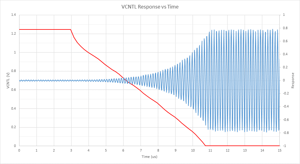
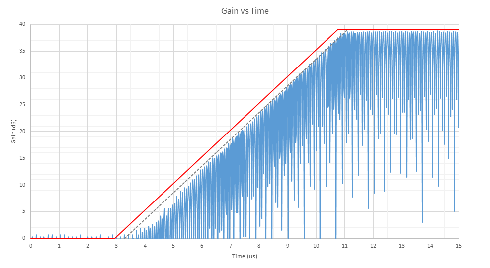
- The results for a 5dB/us slope is shown below.
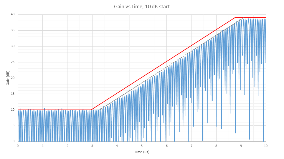
The first image show our VCTRL curve and the sine wave input. The second shows the rectified sine wave converted to a logarithmic scale with the ideal gain curve in red. The gray dashed gain curve is taking into consideration that there is a 0.35us delay. The gap between the gray line and the sine wave is our concern. Between the start and about 6us, there is a significant difference between the two. The slope at the start is very slow. We were expecting a delay, but not such non-linearities. The 800kHz bandwidth for the VCTNL inputs should be sufficient for the slopes we are using. The third curve shows the same slope, but with the gain but with starting at a gain of 10dB instead of 0dB. This curve is ok. Starting from 0dB gain seems to be the problem.
Is there something we can do about this? Are we doing something wrong?
Thanks,