Because of the Thanksgiving holiday in the U.S., TI E2E™ design support forum responses may be delayed from November 25 through December 2. Thank you for your patience.

This thread has been locked.

If you have a related question, please click the "Ask a related question" button in the top right corner. The newly created question will be automatically linked to this question.

LDC1312: LDC1312 Coil Design Questions.

Part Number: LDC1312

Dear TI Team,

Coil is designed for FPCB using LDC1312.
The design specifications are as follows.

  1. PATTERN WIDTH : 0.1mm
  2. Pattern Clearance : 0.15mm
  3. Total Length : 980mm ( TOP , BOTTOM Total length)
  4. FPCB, Theckness : 0.2T
  5. Pattern type : Rectangle
Question
Is there a limit to the thickness of the PCB?
We have to design thinner than 0.2T.
The object of the same target is recognized normally in the EVM KIT, but the reaction does not occur in the coil designed with FPCB.
Can you give us a guide on the above FPCB design specification?

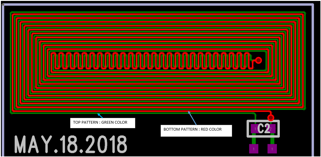
Below is the FPCB we designed.


Thanks.
  • Hi Chun,

    There is no limit to the thickness of the FPCB, as long as it will mechanically work in the system. I would not recommend routing the traces in the zig-zag pattern you currently have at the center of the coil. This will increase your Rs, which will increase your losses in the coil and the amount of current required to keep the sensor oscillating. It would be better to use straight traces, but best to put the via at the left edge of the interior region and remove the excess trace length.

    As for why your target is detectable by the EVM but not by your FPCB coil, I have a few questions. When you tested the EVM with your target, did you use the coil built into the EVM, or did you use one of the coils on the Reference Coil Board EVM? The detection range of the LDC1312 is about 50% of the coil diameter. In the case of your FPCB, this would be about 50% of the shortest diameter of your coil. Your sensor looks like it's about 0.3cm wide at the shortest diameter, so your detectable range would only be about 0.15cm. Is this an acceptable range for your application?

    If your target is within the detectable range of your sensor, are you detecting a smaller change in output codes compared to the original coil you tested, or are you not seeing any change in output codes?

    Regards,
  • Dear Kristin,

    Thank you for answer.

    We are testing using the coil provided in LDC1312 EVM KIT. The design of the FPCB is changed and the test is going to be done again.
    No output was generated for the previously designed FPCB.

    Thanks.
  • Hi Chun,

    When you connected the first FPCB coil, did the resonant frequency match the expected valued based on your FPCB inductor and sensor capacitor values? Or were you unable to get the sensor to oscillate correctly?

    Regards,