This thread has been locked.

If you have a related question, please click the "Ask a related question" button in the top right corner. The newly created question will be automatically linked to this question.

AWR1642: LVDS Format Mapping

Part Number: AWR1642

Hi Community,

Currently I am streaming raw ADC data over two LVDS lanes.

There is some confusion on my side concerning the data format in non-interleaved mode.

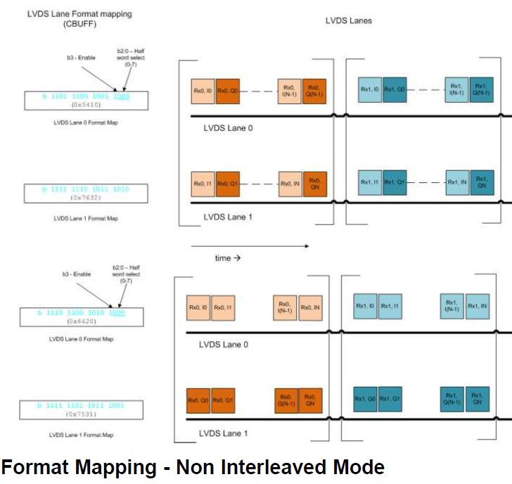
Referring to the Data Path User Guide there are two modes for the LVDS lane format mapping (Figure21)

http://www.ti.com/lit/an/swra555/swra555.pdf 

Searching in the Radar Interface Control Document all I could find was 5.16.6 Sub block 0x4045 – AWR_DEV_LVDS_CFG_SET_SB

Here the format map does only seem to switch lanes but not I/Q as in SWRA555.

Any ideas how to identify the data format?

  • Thank you for your reply Cesar.

    Using the Matlab code for the AWR1642 I am plotting time and frequency domain over one chirp.

    Data was captured with the DCA1000 - I shoud have mentioned before.

    With SetTestSource in mmWave Studio I wanted to verify the PacketReorderZeroFill function from a lua script.

    The output from raw data read is a matrix of [numRx X numSamples*numChirps] complex.

    Starting simple - only absolute values are plotted.

    I expected a smooth sinusodial in time and a distinct peak in frequency domain.

    My results are below.. How can I interpret this?

    Is the DCA1k is sending LVDS data (over Ethernet) in a different manner than described in Figure 12 of SWRA581 since the Matlab code is written for TSW16xx?

    The lua function PacketReorderZeroFill  from mmWave studio should be filtering out Ethernet headers right?

    %% raw data plot + fft for one chirp /w 256 samples
    a = RawDataRead('obj_4-3.bin');
    sample = (0:1:255);
    f = (0:1:255);
    f_bin = (0:1:length(a)-1);
    a = a(1,:);         % ADC0 data only
    b = fft(a(1:256));
    
    figure(1);
    plot(sample, a(1:256));
    
    figure(2);
    plot(f, abs(b));

  • Hello Robert,

    Can you try plotting the same set of data using Radar Studio? This way we can verify if the issue is related to the Matlab script.

    Regards,

    Adrian
  • Hi Adrian,

    the Matlab Post Proc works just fine.

    Until now I was sending CLI commands over Demo Visualizer and recording with the software screenshotted below.

    When I try PacketReorderZeroFill and StartMatlabPostProc in mmWave Studio it gives a 'no frame config information' error.

    How can I access the lua command function for ar1.StartMatlabPostProc()?

    Is there a fix?

    Regards,

      Robert

  • Since the Matlab script in www.ti.com/.../swra581.pdf did not work properly,
    I was wondering if there is documentation on the ar1.PacketReorderZeroFill lua function - since it's only .exe
    Since mmWave Studio processing works this would definitely help with reordering

  • Hello Robert,

    That script is made based on plotting data from the Capture Demo. It looks like data captured using the DCA1000 is a different format. Let me get in contact with the someone more familiar with the DCA1000 capture card and see if there is any difference in the data format or any documentation on the packet reorder utility.
  • Hello Robert,

    I would suggest taking a look at the mmWave Studio User's Guide. IF you have not already downloaded mmWave Studio, you can do so here:

    Once you have installed mmWave Studio, you can find the User's Guide at C:\ti\mmwave_studio_<version_number>\docs. The packet reorder utility is explained in Section 3.2 and the data format is explained in Section 22.

    Regards,

    Adrian

  • Thank you Adrian.

    Chapter 22 'Format of the raw captured file' section 8./9. for the AWR1642 solved the issue.

    The data format was already signed int16 - not uint16

    The attached Matlab script can reorder real and complex .bin files for further processing.

    %%% Script for reordering DCA1000 LVDS stream with 2 lanes
    %%% capture format can be found in mmWave Studio User's Guide 22.8./9.
    
    function [retVal] = readDCA(fileName)
    %% global variables
    % change based on sensor config
    %----------------------------------------------------------------------
    numADCBits = 16; % number of ADC bits per sample
    numADCSamples = 256; % number of ADC samples per chirp
    numRx = 4; % number of receivers
    chirpSize = numADCSamples*numRx;
    numLanes = 2; % do not change. number of lanes is always 2
    isReal = 0; % set to 1 if real only data, 0 if complex data0
    %-----------------------------------------------------------------------
    %% read file
    % read .bin file
    fid = fopen(fileName,'r');
    adcData = fread(fid, 'int16');
    fclose(fid);
    fileSize = size(adcData, 1);
    % one chirp only
    %adcData = adcData(1:chirpSize,1);
    %% organize data by LVDS lane
    % for real data, each Rx in column
    if isReal
        LVDS = zeros(1, length(adcData(:,1)));
        LVDS = reshape(adcData(:,1), [], numRx);
    else
    % for complex data
    % LVDS row with half length
        LVDS = zeros(1, length(adcData(:,1))/2);
    % combine real and imaginary parts
        counter = 1;
        for i=1:4:fileSize-1
                LVDS(1,counter) = adcData(i) + sqrt(-1)*adcData(i+2);
                LVDS(1,counter+1)=adcData(i+1)+sqrt(-1)*adcData(i+3);
                counter = counter + 2;
        end
        % create column for each Rx channel
        if numRx > 2
        LVDS = reshape(LVDS(1,:), length(LVDS(1,:))/numRx, numRx);
        end
    end
    %% organize data by chirps
    % 
    
    %% return receiver data
    retVal = LVDS;