This thread has been locked.

If you have a related question, please click the "Ask a related question" button in the top right corner. The newly created question will be automatically linked to this question.

RTOS/IWR1642: How to change rx channel in iwr1642 sorfware?

Part Number: IWR1642
Other Parts Discussed in Thread: UNIFLASH, MMWAVE-SDK, AWR1642,

Tool/software: TI-RTOS

Hi,

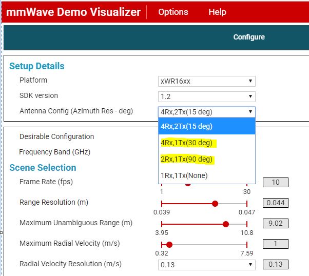
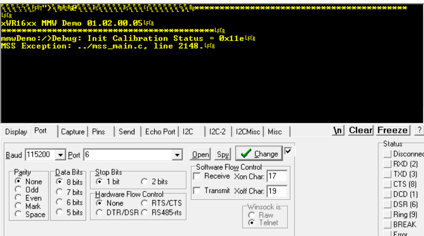
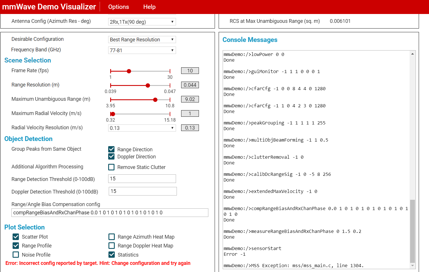
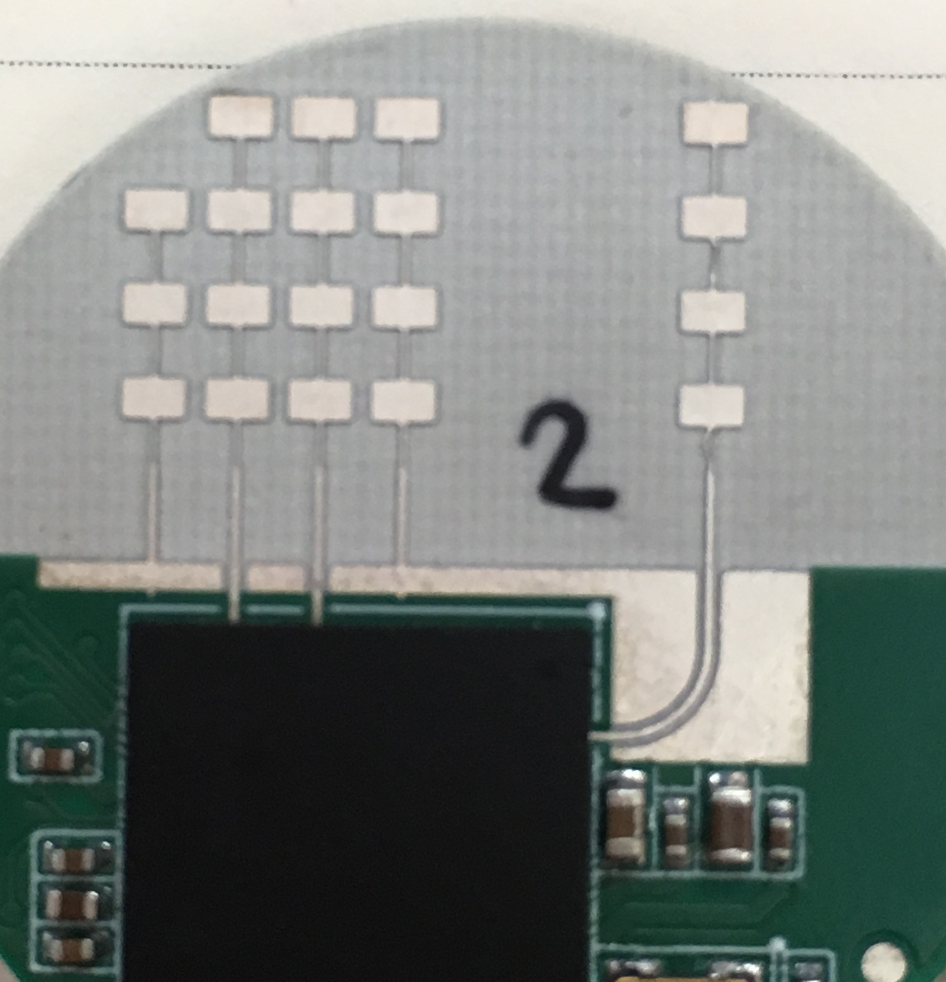
I am working iwr1642 device. I want to use only 2 rx channel(for example : RX1 and RX2) and one tx channel. I have tried to disabled rx channel ,n the source code.But i couldnt do it.Can you please give me any information for this issue? How should i do it?

Thanks.

Naz

  • Hi Naz,

    What's the SDK version you are using for this test?

    If you are using Out-of-box demo from SDK, you can modify the TX/RX channel config in config file.

    2TX4RX: channelCfg 15 5 0

    1TX2RX: channelCfg 3 1 0

    Please find more details in document listed below:

    C:\ti\mmwave_sdk_01_02_00_05\docs\ mmwave_sdk_user_guide.pdf

    Thanks.

  • Hi Wesley,

    I was using mmwave_sdk_01_01_00_02. I have changed with mmwave_01_02_00_05 when you say it. But the result have not change. When I have sent channelCfg 3 1 0 configuration to device isn't working.

    I have looked mmwave_sdk_user_guide.pdf but i couldn't find the solution to the problem.

    Thank

    Naz

  • Hi Naz,

    In the Visualizer, we have the default 1TX2RX setting. You can try it for verification. Thanks.

    Link: 

    Regards,

    Wesley

  • Hi Wesley,

    I have tried and it has happened. Which channels are open to this configuration? Are RX1,RX2 and TX1 channels open or any other channels?

    I have my own design. My design have RX1,RX2 and TX1 channels. Is it suitable for this configuration?

    Regards,

    Naz

  • Hi Naz,

    You can find the channelCfg in console message windows.
    channelCfg 3 1 0 is the default setting in the GUI's default setting.

    Regards,
    Wesley.
  • Hi Wesley,

    This problem hasn't been solved. I have selected 2RX and 1TX channels because my own design place is limited. Therefore i have selected RX1,RX2 and TX1 channels.

    I want this configuration:

    RX1 channel is enabled.

    RX2 channel is enabled.

    RX3 channel is disabled.

    RX4 channel is disabled.

    TX1 channel is enabled.

    TX2 channal is disabled.

    I have sent channelCfg 3 1 0 , channelCfg 3 2 0 , channelCfg 12 1 0 and channelCfg 12 2 0 configurations separately with the my own design GUI. But ı couldnt it.

    channelCfg 3 1 0 --> Which channels are open in this configuration?Are RX1,RX2 and TX1 channels enabled? I am wondering how the configuration is done.Can you give me any information for this configuration?

    We will use "Human and Object Detection Radar For Indoor and Outdoor Applications".  Hence 4RX and 2TX channels are not necessery for my application area. 2RX and 1TX are enough for my design. I want to use only range calculation. 

  • Hi Naz,

    Yes, channelCfg 3 1 0 is TX1, RX1, RX2 enable.
    Please find more details in C:\ti\mmwave_sdk_01_02_00_05\docs\ mmwave_sdk_user_guide.pdf
    Thanks.
  • Thanks Wesley.

    I will try and back you.

    Naz.
  • Hi  Wesley,

    I have tried this channel 3 1 0 cofiguration. And i saw this error in the following ficture:

    Sensor is not starting. Can you give me any information in this error?

    Thanks

    Naz

  • Hi Naz,

    I have try SDK1.1 demo, and I have listed the setting I used for 1TX2RX case test. Could you please double check if you can use the online GUI to set the IWR1642 work in 1TX2RX mode?

    % ***************************************************************
    % Created for SDK ver:01.01
    % Created using Visualizer ver:2.0.0.0
    % Frequency:77
    % Platform:xWR16xx
    % Scene Classifier:best_range_res
    % Azimuth Resolution(deg):90
    % Range Resolution(m):0.044
    % Maximum unambiguous Range(m):9.02
    % Maximum Radial Velocity(m/s):1
    % Radial velocity resolution(m/s):0.13
    % Frame Duration(msec):100
    % Range Detection Threshold (dB):15
    % Doppler Detection Threshold (dB):15
    % Range Peak Grouping:enabled
    % Doppler Peak Grouping:enabled
    % Static clutter removal:disabled
    % ***************************************************************
    sensorStop
    flushCfg
    dfeDataOutputMode 1
    channelCfg 3 1 0
    adcCfg 2 1
    adcbufCfg -1 0 0 1 0
    profileCfg 0 77 916 7 57.14 0 0 70 1 256 5209 0 0 30
    chirpCfg 0 0 0 0 0 0 0 1
    chirpCfg 1 1 0 0 0 0 0 0
    frameCfg 0 0 16 0 100 1 0
    lowPower 0 0
    guiMonitor -1 1 1 0 0 0 1
    cfarCfg -1 0 0 8 4 4 0 1280
    cfarCfg -1 1 0 4 2 3 0 1280
    peakGrouping -1 1 1 1 1 255
    multiObjBeamForming -1 1 0.5
    clutterRemoval -1 0
    calibDcRangeSig -1 0 -5 8 256
    extendedMaxVelocity -1 0
    compRangeBiasAndRxChanPhase 0.0 1 0 1 0 1 0 1 0 1 0 1 0 1 0 1 0
    measureRangeBiasAndRxChanPhase 0 1.5 0.2
    sensorStart
    

    Regards,

    Wesley

    Thanks.

  • Wesley,

    I have sent this configuration in the online and offline GUI:

    mmwDemo:/>% ***************************************************************
    Skipped

    mmwDemo:/>% Created for SDK ver:01.01
    Skipped

    mmwDemo:/>% Created using Visualizer ver:2.0.0.0
    Skipped

    mmwDemo:/>% Frequency:77
    Skipped

    mmwDemo:/>% Platform:xWR16xx
    Skipped

    mmwDemo:/>% Scene Classifier:best_range_res
    Skipped

    mmwDemo:/>% Azimuth Resolution(deg):90
    Skipped

    mmwDemo:/>% Range Resolution(m):0.044
    Skipped

    mmwDemo:/>% Maximum unambiguous Range(m):9.02
    Skipped

    mmwDemo:/>% Maximum Radial Velocity(m/s):1
    Skipped

    mmwDemo:/>% Radial velocity resolution(m/s):0.13
    Skipped

    mmwDemo:/>% Frame Duration(msec):100
    Skipped

    mmwDemo:/>% Range Detection Threshold (dB):15
    Skipped

    mmwDemo:/>% Doppler Detection Threshold (dB):15
    Skipped

    mmwDemo:/>% Range Peak Grouping:enabled
    Skipped

    mmwDemo:/>% Doppler Peak Grouping:enabled
    Skipped

    mmwDemo:/>% Static clutter removal:disabled
    Skipped

    mmwDemo:/>% ***************************************************************
    Skipped

    mmwDemo:/>sensorStop
    Done

    mmwDemo:/>flushCfg
    Done

    mmwDemo:/>dfeDataOutputMode 1
    Done

    mmwDemo:/>channelCfg 3 1 0
    Done

    mmwDemo:/>adcCfg 2 1
    Done

    mmwDemo:/>adcbufCfg -1 0 0 1 0
    Done

    mmwDemo:/>profileCfg 0 77 916 7 57.14 0 0 70 1 256 5209 0 0 30
    Done

    mmwDemo:/>chirpCfg 0 0 0 0 0 0 0 1
    Done

    mmwDemo:/>chirpCfg 1 1 0 0 0 0 0 0
    Done

    mmwDemo:/>frameCfg 0 0 16 0 100 1 0
    Done

    mmwDemo:/>lowPower 0 0
    Done

    mmwDemo:/>guiMonitor -1 1 1 0 0 0 1
    Done

    mmwDemo:/>cfarCfg -1 0 0 8 4 4 0 1280
    Done

    mmwDemo:/>cfarCfg -1 1 0 4 2 3 0 1280
    Done

    mmwDemo:/>peakGrouping -1 1 1 1 1 255
    Done

    mmwDemo:/>multiObjBeamForming -1 1 0.5
    Done

    mmwDemo:/>clutterRemoval -1 0
    Done

    mmwDemo:/>calibDcRangeSig -1 0 -5 8 256
    Done

    mmwDemo:/>extendedMaxVelocity -1 0
    Done

    mmwDemo:/>compRangeBiasAndRxChanPhase 0.0 1 0 1 0 1 0 1 0 1 0 1 0 1 0 1 0
    Done

    mmwDemo:/>measureRangeBiasAndRxChanPhase 0 1.5 0.2
    Done

    mmwDemo:/>sensorStart
    Error -1

    mmwDemo:/>MSS Exception: mss/mss_main.c, line 1304.

    I have have this error both of gui configurations. Sensor is not working. I have saw the following error:

    Regards,

    Naz

  • Hi Naz,

    Are you using IWR1642EVM, could you please check the items listed below:

    • Did you flash the correct BIN file to device?
    • Could you please replace another 5V2A or 5V3A power supply to try it again?
    • Did you try other EVM and other default configuration?
    • What's the 1443 version? ES2.0?

    Regards,

    Wesley

  • Wesley,

    I think i gave wrong information on my project. My project like in this following picture:

    So i have only 2RX and 1 TX antenna channels.

    I have wrote .bin file (in the SDK 01.02.00.05 version) in the QSPI flash using uniflash program. And I have loaded source code(in the SDK 01.02.00.05) in the iwr1642 using CCS. Then I have tried to run sensor using mmWave Visualizer online and offline version,but sensor didnt work. 

    When i sent to channelcfg 3 1 0 (for 2RX and 1TX channel)and sensor want to start i have see this error: 

    xWR16xx MMW Demo 01.02.00.05

    ******************************************

    mmwDemo:/>Debug: Init Calibration Status = 0x11e

    MSS Exception: mss/mss_main.c, line 2148.

    I have checked AR_RS232TX,AR_RS232TX and AR_MSS_LOGGER connection but i couldnt see any mistake. 

    Could you  suggest any idea for me?

    Thanks,

    Best Regards,

    Naz

  • Hi Naz,

    This board is nice.
    I recommend you use IWR1642EVM to test 1TX2RX's configuration and BIN file. After the configuration is correct, you can try it on your own board.

    Regards,
    Wesley
  • Hi Wesley,
    I used IWR1642EVM to test 1TX2RX's configuration and bin file. IWR1642EVM board worked in this configuration. But my board didnt work the same configuration.


    Is there anything else I need to do?

    Regards,
    Naz
  • Hello,

    The error indicated shows that the BSS tried to do a calibration.    If you download Radar Studio or mmwave studio, under the c:\ti\(install folder)\docs, there is an ICD document that has more information.  Under Calibration mask  (AWR_RF_INIT_CALIBRATION_CONF_SB function, the Calibration return value, is supposed to have a value 1 for OK.  Check the line of C that is indicating a problem.

    Note: if you have an IWR1642 ES2 you need to use a different Uniflash, file, and a different mmwave SDK vs IWR1642 ES1 (older EVM).

    In the case of IWR1642, please check the device revision.   There are special requirements for ES1 - which includes the BSS+MSS+DSP, while the newer ES2 requires a BSS patch (not complete code) + MSS+DSP.  There is a different mmwave SDK version for this.

    You can tell the version by looking at the part labeling, or electronic signature with CCS.

    Part marking - The device has a "502" marked in the lower left corner (dot marking is upper left corner) for ES1 - should match you older EVM

                            "502AC" this is an ES2 released part.  you need to use the different mmwave SDK for this part.     

    ES2 - 

    2.00.00.04  26-APR-2018  Latest MMWAVE-SDK release. Supports AWR1642 ES2.0, AWR1642 HS ES2.0, IWR1642 ES2.0, and IWR1642 HS ES2.0. 

    Regards,

    Joe Quintal

  • Hi Joe,

    I have preproduction(XI1642QGABL)  iwr1642 which both iwr1642evm and my board. I have tried SDK 01.01.00.02 and  SDK 01.02.00.05. IWR1642EVM have worked for 1TX2RX. But my board didnt work. I have saw the same error.

    I dont understand where i am making mistakes.


    Is there anything else I need to do?

    Thanks

    Regards

    Naz

  • Hello,

    The calibration error is causing the mmwave software not to run the radar.  0x11e indicates that several of the calibration commands failed.

    If I flash the 1.02.05 mmw demo software on the EVM, and run the Visualizer with 1.2 SDK ver, best range resolution.  The Calibration status in the terminal window is

    mmwDemo:/>sensorStart

    Debug: Init Calibration Status = 0x7fe

    I have saved the EVM configuration file, and modified ChannelCfg 3 1 0 - to correspond to Rx1, Rx2, and Tx1 active

    Changing the Chirp configuration as there is no Tx2

    change the frameCfg to loop over chirp 0 only for 32 cycles.

    Looking at your picture, there is stripline delamination for the Tx antenna.  The stripline near the antenna should be straight.

    Done

    In your case you have reported, mmwDemo:/>Debug: Init Calibration Status = 0x11e

    this means calibration has failed for  bits, d11, d10, d7,d6,d5

    Using the Radar Studio ICD document, and the mmwave SDK User Guide, I have attached the modified Visualizer configuration which runs for the EVM

    the calibration status should be 0x7fe.

    The radar studio AWR1xx Radar Interface Control Document, in the docs folder of the mmwave Studio installation, (pg 154) indicates failure for

    11 - Tx Phase calibration

    10 - Rx gain calibration

    7 - LPF cutoff calibration

    6 - HPF cutoff calibration

    5 - Rx ADC DC offset calibration

    I will ask the design engineer, the calibration may be affected by the number of connected Tx and Rx ports.

    On your board you can check the following 

    I will use the IWR1642 BOOST EVM schematic as a reference, please also review the IWR1642 Hardware Checklist - 

    please check that the power supplies meet the intended voltage

    - 3v3, and 1v2 are used for digital core - follow 5% specification limit for setpoint, ripple, and noise tolerance

    - 1v3_RF1, 1v3_RF2 - 1.3v 5% tolerance, datasheet table 5-2 for 1v3 ripple and noise 

    - 1v8, several loads, we can check one supply connection 1.8v 5% tolerance, datasheet table 5-2 for 1v8 ripple and noise

    There are internal voltage regulators, these can be checked at the external bypass capacitors (I am referencing the EVM schematic IWR1642BOOST.

     AR_1v4_Synth C14 - should be 1.4v +/- 5%, ripple and noise should be within the Table 5-2 ripple and noise for 1.8v  (voltage is 1.4v)

      AR_1v4_APLL C13 - same as above

      AR_VOUT_PA - 1v - should have ripple and noise within Table 5-2 for 1v

    Also please check multiple boards, if you have the same error.

    I have attached my script.

    iwr1642_bestrangeres_Rx12_Tx1_visualizer.cfg

    ICD document

    1205.AWR1xx_Radar_Interface_Control.pdf

    IWR1642 Hardware Checklist

    1780.HardwareDesignChecklist_V0p7_IWR1642_SWRR151.xlsx

    Regards,

    Joe Quintal

  • Hi,

    I have checked 3V3,1V2,1V3 and 1V8 voltages. All of them is correct.

    I have checked the other voltages:

    -AR_1V4_SYNTH and AR_1V4_APLL voltages is equal to ~1.4V.

    -AR_VBGAP and AR_VOUT_PA voltages is equal to ~0.9V.

    I have checked the hardware checklist but i didnt see any mistakes.

    I will ask the design engineer, the calibration may be affected by the number of connected Tx and Rx ports. -->  Did you ask this question?

    I  have saw ICD document, how does should i BSS configuration change? 

    Thanks.

    Regards.

    Naz 

  • Hello,

    The BSS software engineer indicates you should be using DFP 1.0 or greater.  

    Please check that on your hardware module, Rx3, and Rx4 should not be floating, they should be tied to GND or to a 50 ohm resistor to GND.

    Tx2 as an experiment can be tied to a 50 ohm resistor to GND.

    If you look at the ICD document, there should be a function when you set the mask for calibration.   The current mask should be 0x7fe,  In your case with

    0x11e, there are several failing tests.  Trace through the software and set the calibration mask to 0x11e, before running the calibration API.  This is only for debugging, but should allow the RF initialization.  

    Regards,

    Joe Quintal