This thread has been locked.

If you have a related question, please click the "Ask a related question" button in the top right corner. The newly created question will be automatically linked to this question.

AWR1443: About 2D-FFT

Part Number: AWR1443

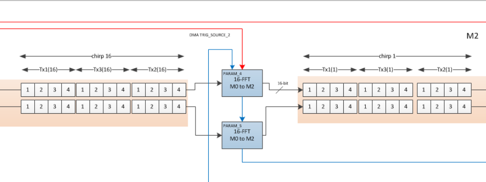
When 1D-FFT makes a 256-FFT, and it's reflected in 256bins in L3_Radar_Cube(256*(3*4*16)). But  when it's 2D-FFT, in the programm can man see it's 16-FFT, but it's not reflected in the image named "datapath_2d_detailed_elevation" ,in that pic the data in M0(2*(3*4*16)) after 2D-FFT still a 2*(3*4*16) matrix ,and although finally after SUM it's a 2*16 matrix, but i think it represents 16 chirps, SO how to explan that?

And talks to 16 chirps, does It correspond to "discrete single in 2D-FFT(online lesson)",and the  time interval between 2chirps corresponds to the interval between 2 sampls, In other words, the 2D-FFT uses the phase (for ω) of 16 chirps, so the FFT-result for 12 virtual antennas are same, SO is my understanding right?

And as it says in the online lesson, the 2 Axis of L3_RangeDopplerLogMag are stand for range and velocity, so 256 -> range, 16-> velocity , SO isn't it bad for velocity's accuracy(case i think 16 is too samll)

  • Hi,

    Did you have a chance to review the detailed mmWave SDK demo documentation provided in:

    C:\ti\mmwave_sdk_01_02_00_05\packages\ti\demo\xwr14xx\mmw\docs

    It should answer most of your questions

    thank you
    Cesar
  • actually that‘s where i find those questions
  • What you see in the accelerator memories (Mx) are the ping and pong worth of processing so in both range and doppler processing, the Mx is holding part of the data. The full data is in L3 memory in radar cube and the dimensions of that are same after 1D or 2D processing. You are comparing apples and oranges when referring to radar cube of 1D output and the Mx of 2D FFT output, see the radar cube for 2D output (this is for the low precision case where we store the radar cube from 2D into L3 but in high precision processing we do not store the radar cube in L3, we recompute 2D during angle processing). The 1D performs only in the range dimension and 2D then acts on this output to do FFT in the doppler dimension. The 16 chirps are virtual, they are each made up of 3 physical chirps corresponding to the three tx antenans in TDM-MIMO configuration, the doppler dimension is thus 16. The doppler FFT is done on the samples corresponding to the same transmit antenna. For each range-doppler bin (consisting of 4*3 = 12 virtual receive antennas), the sum is accumulating log2abs the 12 virtual antennas and storing output in detection matrix. The 16 case is an illustration case in the documentation, the actual configuration is user controlled.

  • 16 stiil makes me confused, the matrix in M2 in this pic actually is 2*(3*4*16)after 16-FFT, and after SUM, we've got a 2*16matrix, i think "16" in L3_rangedopplerLogMag is the num of chirps

    so i can't see the result of 16-FFT,in my opinion, after 16-FFT the num of chirps can't be seen in the M2, maybe "16"in M2 is stand for 16FFT and it's a mistake in that pic?

  • I don't know if I understand your confusion right, but the PARAM_x box that shows 16-FFT is doing the FFT on each of the 3*4 (1,2,3,4) i.e it collects all the "1" (rx1) of Tx1 (16 of them) and performs the 16-point FFT on them and scatters the result across into the M2 in the same order as the input, then all of the "2" of Tx1, ... all of the "4" of Tx1, then all of the "1" of the Tx3 and so on. The gathering from the input side (M0/M1) and scattering on the output (M2/M3) in the same order as input is done with proper programming of the Param set's address jumps [I assume you have read the HWA UG]. The 16 is the doppler FFT dimension (this is TDM-MIMO), it is the number of virtual chirps, the physical chirps = 3 (num tx) * virtual chirps. The log2abs will convert the 32-bit complex numbers into 16-bit real numbers (hence the boxes are shows a bit smaller) and has same arrangement in the output as input. Then sum will sum all 3*4 virtual antennas of this log2abs output and this sum is output in the M memory after the 2D output of M so both can then be EDMA-ed out to their respective positions in the l3 memory.
  • almost clear but one point: i still think the result of 1D_256_FFT is Intuitiver, case i suppose each bin represent for a frequency_point, but here in 2D_FFT, when a higher_FFT (e.g 64 FFT) is done, all "1"TX1 bins are not enough to represent each frequency_point?
    Above is my confusion, by the way , i'm wonder that what the data is in each bin? i can't make a connection between that and the Spectrogram, i think that's maybe helpful for my confusion above.
    Thanks.
  • Presently in the demo we require that the number of virtual chirps (number of physical chirps / num Tx) to be power of 2 and so number of doppler bins is same as the number of virtual chirps. But if we were to do a higher FFT as you mentioned to say increase the accuracy of doppler estimation, then there will be zero padding done automatically by the hardware accelerator and the output will be an amount equal to the larger size (64) even though the input is 16 but it will still be scattered as shown in M2/M3 memory and we would need to label as doppler bin 1, doppler bin 2,... doppler bin 64 (say i.e 16->64) instead of chirp 1, chirp 2,.. labeling. Currently also we could label as doppler bin 1, ... doppler bin 16 instead of (virtual) chirp1, chirp2, ..labeling, it is the same.