This thread has been locked.

If you have a related question, please click the "Ask a related question" button in the top right corner. The newly created question will be automatically linked to this question.

IWR1443BOOST: Thoughts on own measurement results

Part Number: IWR1443BOOST
Other Parts Discussed in Thread: IWR1443

Hello everyone,

like stated in another thread (https://e2e.ti.com/support/sensor/mmwave_sensors/f/1023/t/695708

I designed a waveform for up to 50m and took some measurements in ~5m steps from 5 to 50m with an object in boresight. I was using a corner reflector with about 110 m².

The measurements were taken outside on an area with asphalt. So I calculated the theoretical SNR as well as CNR (clutter to noise ratio) and based on this the SCNR. I then compared these theoretical values with my actual measured values.

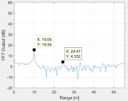
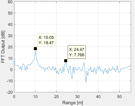
In this plot you can see the mentioned values (sorry for the missing axes labels - x axis: range in m, y axis: power in dB):

So you can see that the "measured SNR" curves matches the SCNR better than the SNR curve (no surprise). But there is also a difference of about ~25 dB.

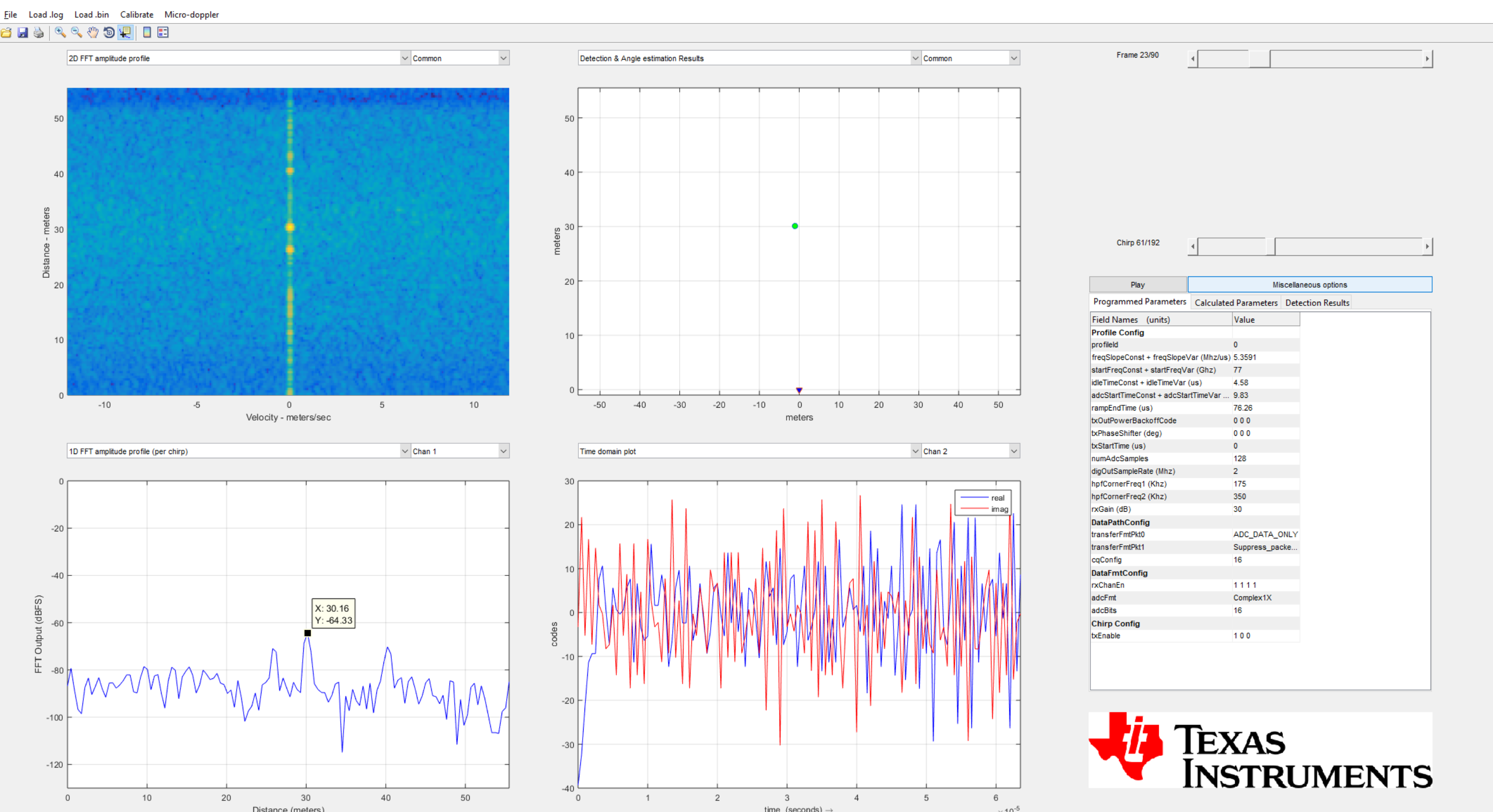
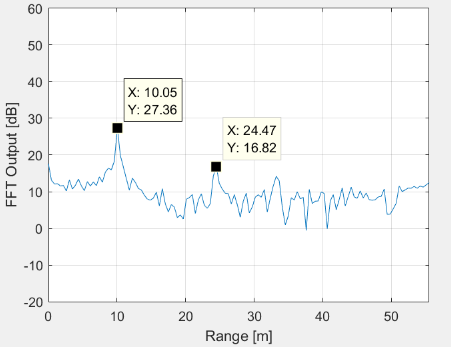
I was wondering where this difference comes from. I first thought about saturation, because the RCS of the reflector is quite high. But I think that you should see this in the "FFT Output" of the PostProc tool in dBfs (because it then should be higher, right?).

Do you have any ideas of this? Can you please give me any hints on where to look at or where this huge mismatch / gap of theoretical ad measured values could be based on? (I know that errors of ~10 dB are not unlikely, but I think 25 dB is a lot).

Thank you very much,

Enric

You can take information about the config I used from this screenshot (target was at ~30m):

  • Hi Enric,

    I've asked an expert to look into your query and someone should have an answer for you today.


    Cheers,
    Akash
  • {
        "platform": "xWR1443",
        "num_rx": 4,
        "num_tx": 1,
        "tx_gain": 8,
        "rx_gain": 8,
        "frequency_range": "77 - 81",
        "maximum_bandwidth": 4000,
        "tx_power": 12,
        "ambient_temperature_degC": 20,
        "maximum_detectable_range": 50,
        "range_resolution": 5,
        "maximum_velocity_kmph": 15,
        "velocity_resolution_kmph": 5,
        "measurement_rate": 10,
        "typical_detected_object": "3",
        "detection_loss": 2,
        "system_loss": 1,
        "implementation_margin": 2,
        "detection_SNR": 12,
        "maximum_radar_cube_size": 256,
        "maximum_RF_bandwidth": 15,
        "maximum_sampling_frequency": 18.75,
        "sensor_maximum_bandwidth": 4000,
        "maximum_allowed_bandwidth": 4000,
        "starting_frequency": 77,
        "maximum_velocity": 4.166666666666667,
        "velocity_resolution": 1.3888888888888888,
        "idle_time": 7,
        "adc_valid_start_time": 12.2,
        "excess_ramping_time": 1,
        "periodicity": 100,
        "ambient_temperature": 293.15,
        "noise_figure": 16,
        "num_virtual_rx": 4,
        "non_coherent_combining_loss": 2,
        "rcs_value": 1,
        "combined_factor_in_dB": -7,
        "combined_factor_linear": 0.19952623149688797,
        "valid_sweep_bandwidth": 3000,
        "inter_chirp_time": 20.2,
        "aux_comp_coeff_a": 78500000000,
        "aux_comp_coeff_b": -16377700,
        "chirp_time": 208.63312101910827,
        "ramp_slope_init": 14.379308449904444,
        "ramp_slope_parameter": 298,
        "ramp_slope": 14.387369155883789,
        "aux_comp_T1": 1,
        "maximum_beat_frequency": 4.79578971862793,
        "sampling_frequency": 5.328655242919922,
        "number_of_samples_per_chirp": 1112,
        "total_sweep_bandwidth": 3192.313272857666,
        "idle_time_minimum": 7,
        "ramp_end_time": 221.88304465324384,
        "carrier_frequency": 77.17552840952642,
        "aux_comp_T2": 3.4,
        "adc_valid_start_time_2": 4.4,
        "lambda": 3.887242577829483,
        "max_chirp_repetition_period": 233.2,
        "chirp_repetition_period": 228.9,
        "num_range_fft_bins": 2048,
        "min_num_of_chirp_loops": 7,
        "max_range_for_typical_detectable_object": 39.50889288871188,
        "min_rcs_detectable_at_max_range": 2.5650780057263844,
        "num_doppler_fft_bins": 8,
        "active_frame_time": 1.8312,
        "range_inter_bin_resolution": 2.71484375,
        "velocity_inter_bin_resolution": 1.2152777777777777,
        "radar_cube_size": 224
    }
    Hello,

    I would first enter you requirements into the Sensing Estimator tool, to check the profile and frame configurations.  Looking at the time series,

    you have a low magnitude count.   Please check under the profile configuration Rx LNA Gain (24-48) and Gain Target (26-34) that you can range

    with the highest Rx signal level.   Your picture says the Rx LNA gain is 30db.  

    You can convert the Sensing Estimator to the Radar Studio / mmwave studio, you need to match up the json file output to the profile, frame configuration.   I have attached 2 files.

    Regards,

    Joe Quintal

  • Hey Akash, thank you for forwarding my request!

    Hey Joe,

    thank you for your answer!

    Yes, at first I entered my requirements into the Sensing Estimator tool. But I think the Sensor Estimator is more used, to get a quick impression. The SNR is not really involved in calculating the chirp / frame parameters at the sensor estimator.

    I used another approach for my requirements. Main priority is to reliably detect a small object at max range. So I need to maximize the SNR. With limitations due to radar memory (384 KB with IWR1443) I chose 128 samples per chirp and 192 chirps per frame. To maximize SNR, the chirp time (more precisely: the sampling time) needs to be maximized. Therefore I took the smalles possible sampling rate (2MHz). Theoretically, the chirp parameters are valid for my requirements.  But unfortunately there are big differences (25 dB) between theory and experiments.

    What do ou mean with "low  magnitude count"?

    And what do you mean with "Please check under the profile configuration Rx LNA Gain (24-48) and Gain Target (26-34) that you can range with the highest Rx signal level"? I am sorry, but the meaning of "Receiver Gain" and "Gain Target" were not really clear to me before.

    And you are correct, the Receiver Gain was at 30 dB.

    A few days ago I already took some measurements with the same reflector at a range of 10 meters and variated the receiver gain (24 dB, 30 dB and 48 dB). I thought that I maybe would get a better understanding of that parameter. But I did not.

    Below you find pictures for those measurements attached.

    24 dB:

    30 dB:

    48 dB:

    So from 24 to 30 dB, I noticed a increase in the peak values of the targets of about 3 dB, while the noise and clutter level is constant.

    From 30 dB to 48 dB I think the peak values of the targets as well as the signal and clutter level went up by about 10 dB.

    Do you have any advice for me?

    Thank you,

    Enric

  • Hello Enric,
    Looking at the I and Q count values is important as well as the FFT. If the receiver is not in compression, you should be able to
    increase Rx LNA gain (and Rx LNA Gain target to max setting), you should see a linear increase in the time series, and we would expect
    the SNR to increase or stay the same. Only if we are near the 16bit signed full scale, would we not increase the RxLNA further.

    I see a 10db increase in signal peak for an 18db gain change. Please look at the IQ time series, it should be higher than 100 counts for I and Q with 48db of LNA gain.

    Please start with a 5 - 10meter target coke can full of water, or tennis ball wrapped in aluminum foil. You should have at least a 20db SNR from the placed RCS target, if there are no other objects.

    Regards,
    Joe Quintal