This thread has been locked.

If you have a related question, please click the "Ask a related question" button in the top right corner. The newly created question will be automatically linked to this question.

IWR1443: IWR1443 RF questions

Part Number: IWR1443

Dear,

I have some question about the RF performance:

1. How to calculate the radar sensitivity. The simplify receiver sensitivity formula is Sv=NoiseFloor+10lgBandwidth+NF+DemodulationThreshold   

What number should NoiseFloor, Bandwidth and DemodulationThreshold use in your FWCW radar?

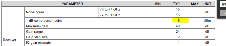
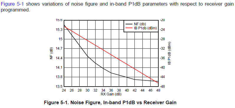
2. Receiver P-1dB spec. 1-dB compression point spec is -5dBm in table, however the in-band P-1dB is less than -20dBm in below figure.

What is the different?

  • Hello,

    Q1) Typically to calculate if the FMCW radar system design works, we would use a spreadsheet with the Radar Equation, or the Sensing Estimator Web tool.  

    The Receiver in ths radar-system is capable of detecting objects C3 above the noise clutter level.  The RCS is set in C2, the max range is calculated in C24.

    Q2)The difference for the table,  is that this is at the Rx input before the LNA, and is supposed to be within the Radome reflection frequency which gets filtered with the HPF1, and HPF2 filter.   Figure 5-1 shows the affect on the Receiver with a specific inband signal strength,  the Rx LNA has a range of 24-48db split between 2 stages, along with the 2 HPF filters.    -23dbm  with 24db gain, -35dbm with 36db gain, -47db with 48dbm gain .

    linkbudget.xlsx

    Regards,

    Joe Quintal

  • Joe,

    Q1 ) According the calculation in spreadsheet, the Noise Bandwidth is equate to inverse of integration time?
    Q2 ) The -5dBm P-1 in table indicate the signal which is reflected in very close distant by radome, unmatched RF circuits or something else, this signal can be filtered by HPF1 and HPF2, right? The P-1 in figure is the in-band signal which will not be filtered by HPF and will be detected?

    thanks
    LY
  • Hello LY,

    Q1)  Using the spreadsheet I sent, and evaluating Cell C22, this is a re-arranged form of the equation for noise floor dbm in

    "en.wikipedia.org/.../Minimum_detectable_signal   "

    Normally the integration time  would correspond with the DFE output rate as 1/Integration time ms, would be  khz.

    Related to Level Sensing use case, as the max range is greater, the System Loss above the liquid in the tank is higher, the Directional gain in the Tx and Rx antennas needs to increase.  (there is also Rx LNA Gain) 

    We normally have a 512 or 1024 point FFT.  The chirp parameters for FMCW can be customized so that 100% of the tank range is 90% of the available DFE Complex 1x output rate.  We typically use 4 or 8 chirps, with non coherent combining to increase the peak signal (increase SNR).

    Q2) the HPF1, HPF2 should filter out of band signals.  So the -5dbm PQ is filtered by the HPF.  (out of band is  lower frequency than  HPF @ desired attenuation)

    The figure that shows LNA gain. and Noise Figure is for inband signals which are passed (not attenuated)

    Regards 

    Joe