This thread has been locked.

If you have a related question, please click the "Ask a related question" button in the top right corner. The newly created question will be automatically linked to this question.

AWR1243BOOST: Dynamic range of ADC raw data

Part Number: AWR1243BOOST

Hi!

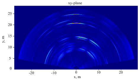
We suppose dynamic range of raw adc data captured with AWR1243BOOST+TSW1400 to be 0 ... 65536 (16 bit), but saved data have less than 5% of this range. Such performance comes out in various surroundings, in presence and/or absence of strong reflectors. Can someone clarify this issue?

Thanks!

  • Were you able to process the captured data in matlab to check if you are able to detect the corner reflector?

    Thank you
    Cesar
  • Hello, Cesar.

    Thank you for quick response!

    Yes, we have processed the data, and corner reflector is seen clearly as you can see in attached picture. Here two corner reflectors were placed at 20 and 24 meters from EVM in front of it. Also some constructions are well seen by sides. Processed data looks to be true to surrounding. But maximum and minimum of the inphase component are (960; -1313) and (1396; -957) for the quadrature while 16 bit are used.

    Regards,

    Timur

  • Hi Timur,

    The primary amplitude metric is the SNR of target returns - typically 20dB is good goal. If your SNR is sufficient for your processing requirements then there is no issue caused by the relatively small ADC code ranges you are showing. There is no guarantee that a substantial amount of the full ADC code range is going to be used in any given scene.

    Do you see any problem processing these ADC samples? Is the value of the return changing in response to target RCS, TX backoff and RX gain?

    Thanks,
    Randy

  • Hi, Randy,

    thank you!

    Results of processing of ADC data are well matching to surroundings even in case of  the relatively small ADC code ranges. And it is clear that the full ADC code range is not guaranteed and depends on given scene as you said. We have experimented with various target RCS, TX backoff and RX gain, and the value of the return is changing as expected.

    But there were no any scene providing saturation or sample values close to maximum 2^15 (16 bit mode is used).

    For example, corner reflector placed in front of radar at 1.5 m brings the next maximum sample values:

    1) TX backoff = 0; RX gain = 30; RCS > 100; inphase (1134; -1042), quadrature (1070; -1053);

    2) TX backoff = 0; RX gain = 40; RCS > 100; inphase (3195; -2933), quadrature (3449; -3406).

    According to 10 dBm power at the ADC input corresponds to peak voltage value, it means in case 1) and 2) mentioned above there are less than -20 dBm and -30 dBm power at the LNA input (since there is no saturation). At the same time my estimation of input LNA power is -36 dBm (TX output P_out = 12 dBm, antennas gains G = 10 dBi, RCS = 100 m^2, distance d = 1.5 m).So it's fit with saturation absence.

    Reducing distance to 0.5 m lead us to -17 dBm at the LNA input, and +13 dBm at the ADC input (if RX Gain = 30) and saturation should be expected. Just now we perform such a test and the saturation was found (with RX Gain = 48)!!

    Is it correct? Pardon for posting the thoughts, possibly it will be usefull for someone.

    Regards,

    Timur.