This thread has been locked.

If you have a related question, please click the "Ask a related question" button in the top right corner. The newly created question will be automatically linked to this question.

DRV5032: Detecting the number of rotations with hall sensor DRV5032 with ultra low power

Part Number: DRV5032
Other Parts Discussed in Thread: MSP430FR2000, DRV5012

Dear all,

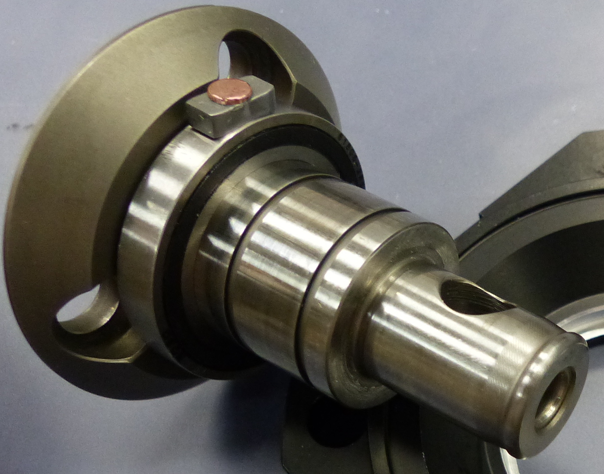
we are looking for a solution to count the number of rotations of a rotating axis (< 10Hz) using a battery powered ultra low power solution. (DRV5032 with MSP430FR2000)

On the rotating axis there is a magnetic pin which should trigger the counter. At the moment we are using a reed switch, but we are looking for a more battery saving option.

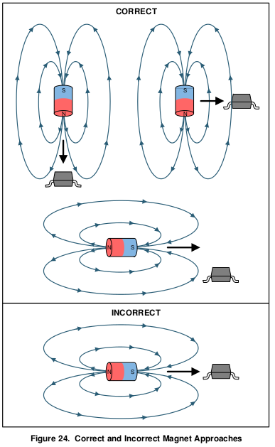
The sensor must be put into a tube or screw casing with max. 4mm diameter, which makes it difficult to arrange sensor and magnet as given in the datasheet:

We now need to know if it is possible to to detect the rotation with the DRV5032 with the orientation as given in the below illustration:

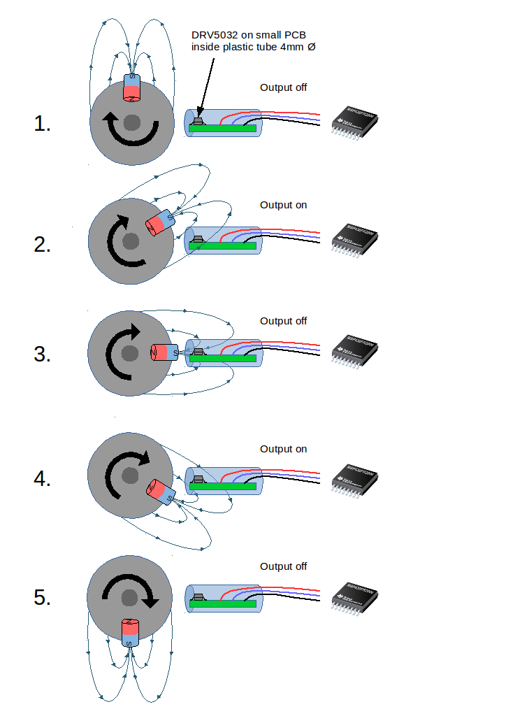
With this approach we expect to get two counts with each rotation. Is this a possible and/or recommended way to do it? if not, are there any other suggestions?

Many thanks,
Christian

  • Hello Christian,

    Thanks for considering to use Texas Instruments in your design. We are looking into your issue and we will get back to you on the following business day (Monday in the U.S. Mountain Standard Time Region).
  • Hello Christian,

    There are a lot of factors that go into determining if this setup will work, so I have a few questions for you so that I can better help you.

    1. What is the size and type of magnet?
    2. What is the diameter of the wheel the magnet will be on?
    3. How far will the sensor be from the magnet?
    4. Can the magnet be rotated sideways, or is its position fixed?
    5. Is 10Hz the fastest the wheel will rotate? If not then what is the fastest?
  • Hey Christian,

    On another note, as long as the magnet is strong enough and close enough to the sensor, then my main concern is with the 10Hz rotation of the magnet. Based on the specific speed of the wheel and the sample rate of the sensor, it may be difficult to tell the difference between step 2 and step 4. Meaning, based on the specific design, the MCU may sometimes see one count and sometimes see two counts each rotation. One possible solution would be to use the unipolar version of the DRV5032 instead, so that you only see only one count at stage 2. This will only work if the magnet is not spinning too fast for the sensor's sampling rate. Once I get the answers to the previously posted questions, then I can help determine if the DRV5032 will work for you, or if you need a sensor with a higher sampling rate.
  • Dear Mitch,

    thanks for your explantations so far. Here is the info you requested:

    • it's a N35 magnet with 5mm diameter and 2mm height
    • the magnet sits on the surface of an axis, distance from center of the axis approx. 20mm
    • the closest distance from magnet to sensor is approx 3mm
    • due to the shape of the magnet, rotation is no option (see picture as reference, the red marked part is the magnet)
    • Maximum speed is 10Hz for this particular application (but we might be looking at higher speeds for similar applications)

    I understand the problem when detecting two pulses. Using the omnipolar version should solve this problem?

    We would like to use a low power sleep mode of MSP430FR2xxx and wake up by sensor pulse, count +1 and go back to sleep. Is this realistic or does the MCU core have to be on all the time?

    Best regards,
    Christian

  • Hey Christian,

    Thank you for your timely reply. I ran a simulation with your design parameters to see the magnetic field strength at the sensor, as shown in the GIF below (Note, the DRV stopped drawing halfway through the GIF, but it was there for the calculation. Click on the image to see the animation).

    The plot below is the output from the simulation (the blue line (By) is the approximate magnetic field strength the sensor will see in your setup, and the magnet is the closest to the sensor at the 90° point):

    From this plot, it seems that the magnetic field strength is strong enough to trip the sensor, as long as you choose the appropriate gain version. In general, using the unipolar sensor will make it so that your sensor trips only one time per revolution, instead of two times.

    However, the DRV5032 will still not work for your design because it only has a sampling rate of 20 Hz. This means that if your magnet is spinning at 10 Hz then the sensor will only check the magnetic field two times per revolution. This means that you cannot guarantee that the sensor will see the magnetic field spikes.

    For your application, I recommend that you use the DRV5012 (Ultra-Low Power Digital-Latch Hall Effect Sensor), operating in the 2.5 kHz mode. This will solve two of your problems at once. Firstly, the 2.5 kHz sampling rate should sample fast enough to see your magnetic field spikes every time. Secondly, since this is a latch device, you will only see one voltage pulse per revolution because the positive magnetic field will turn it on, and then the negative magnetic field will turn it off. Just make sure to align the sensor so that the voltage is on while the magnet faces the sensor and off when facing away to save on power (ie, the voltage output will be high for less time that way).

    About the microcontroller, from my understanding, it is usually fine to have the MCU is sleep mode and then use interrupts to wake the device every time it sees the voltage pulse. However, if you would like more detailed/specific information from the MCU team (based on your specific MCU), feel free to post a question on their e2e forum page. 

    I hope this was able to help, let me know if you have any more questions.

  • Dear Mitch,

    thanks a lot for the analysis and the simulation run!
    This resolves my questions.

    Best regards,
    Christian
  • Glad I could help!