This thread has been locked.

If you have a related question, please click the "Ask a related question" button in the top right corner. The newly created question will be automatically linked to this question.

AWR1243: Phase change in Tx of AWR1243

Part Number: AWR1243

Hi,

I am Using AWR1243 +TSW1400 for data capture in BPM mode.

To verify whether my BPM code (0 and 1) for 64 chirps is being properly applied or not, I captured the RX data for 1 frame (64 chirps) with Only one Tx ON.

The BPM code is different for all the 3 Tx transmitters. And I capture the data for all three Tx one after the other. (One Tx only ON at a time and capture the data 3 times for 3 Tx).

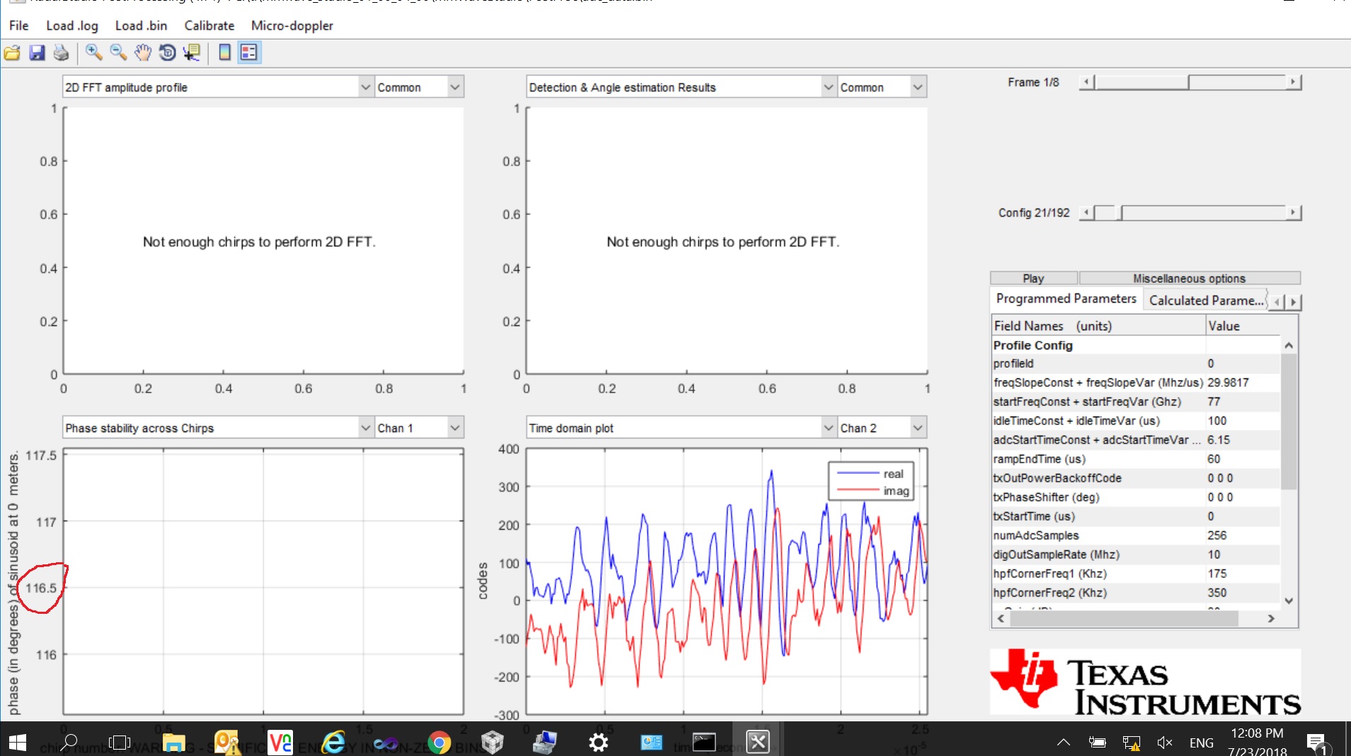
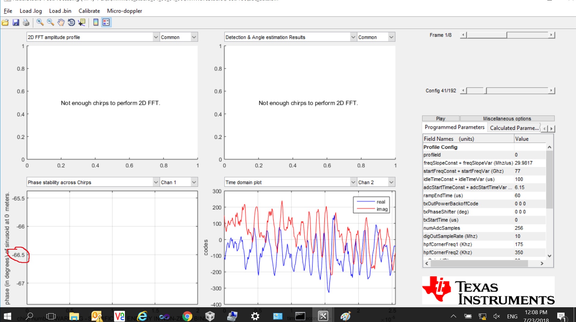
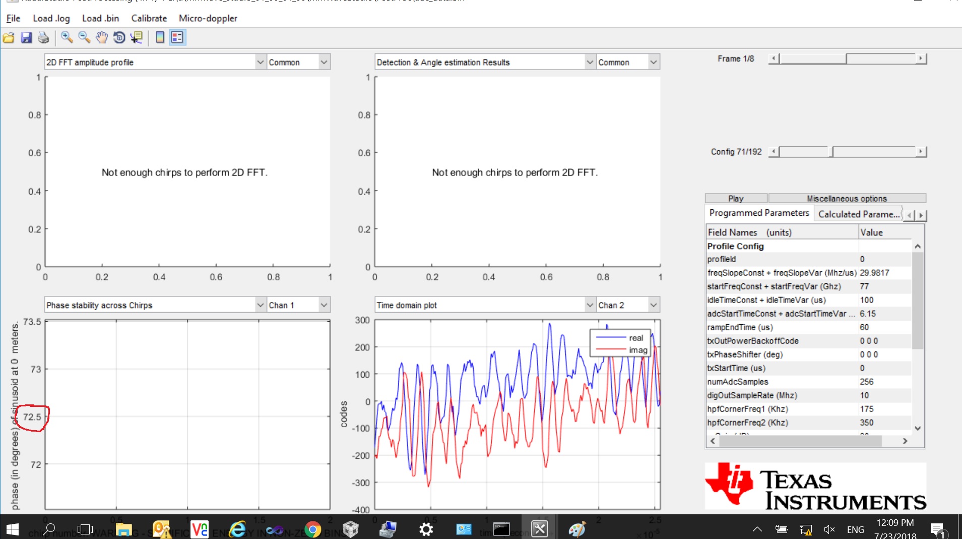
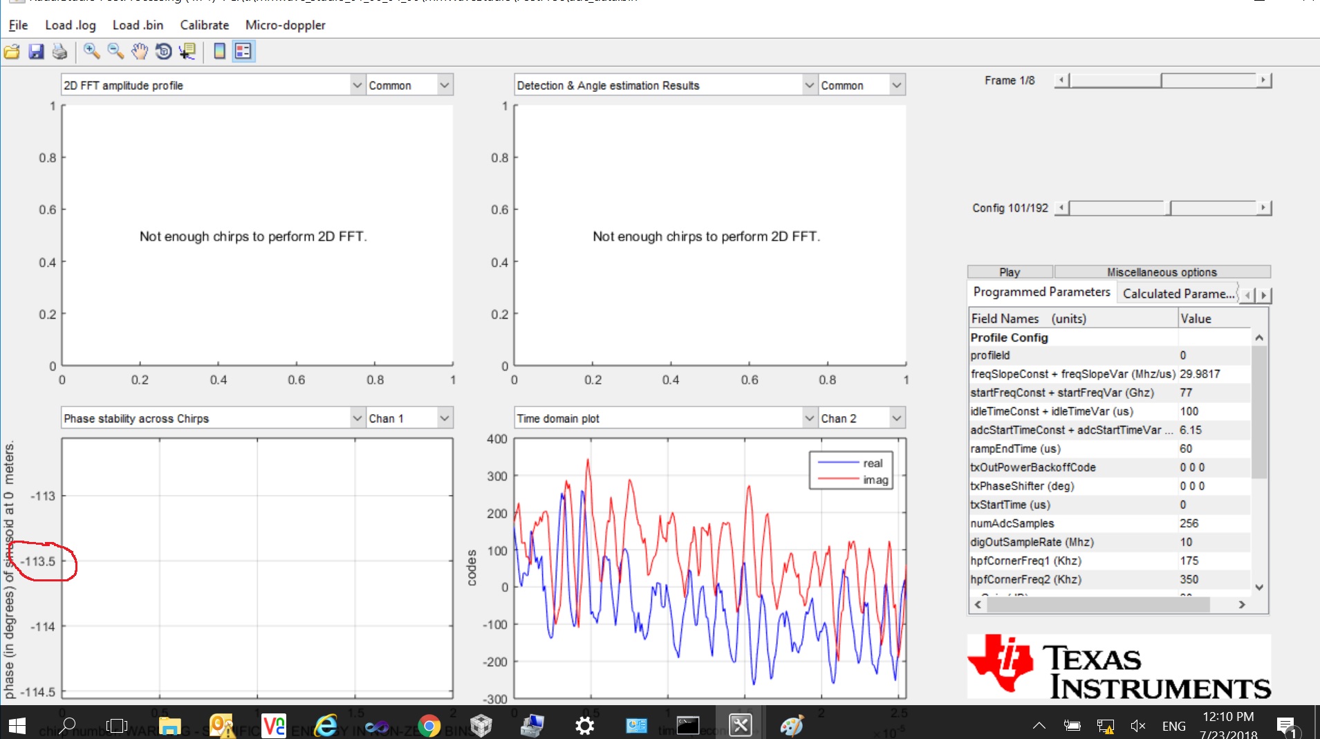
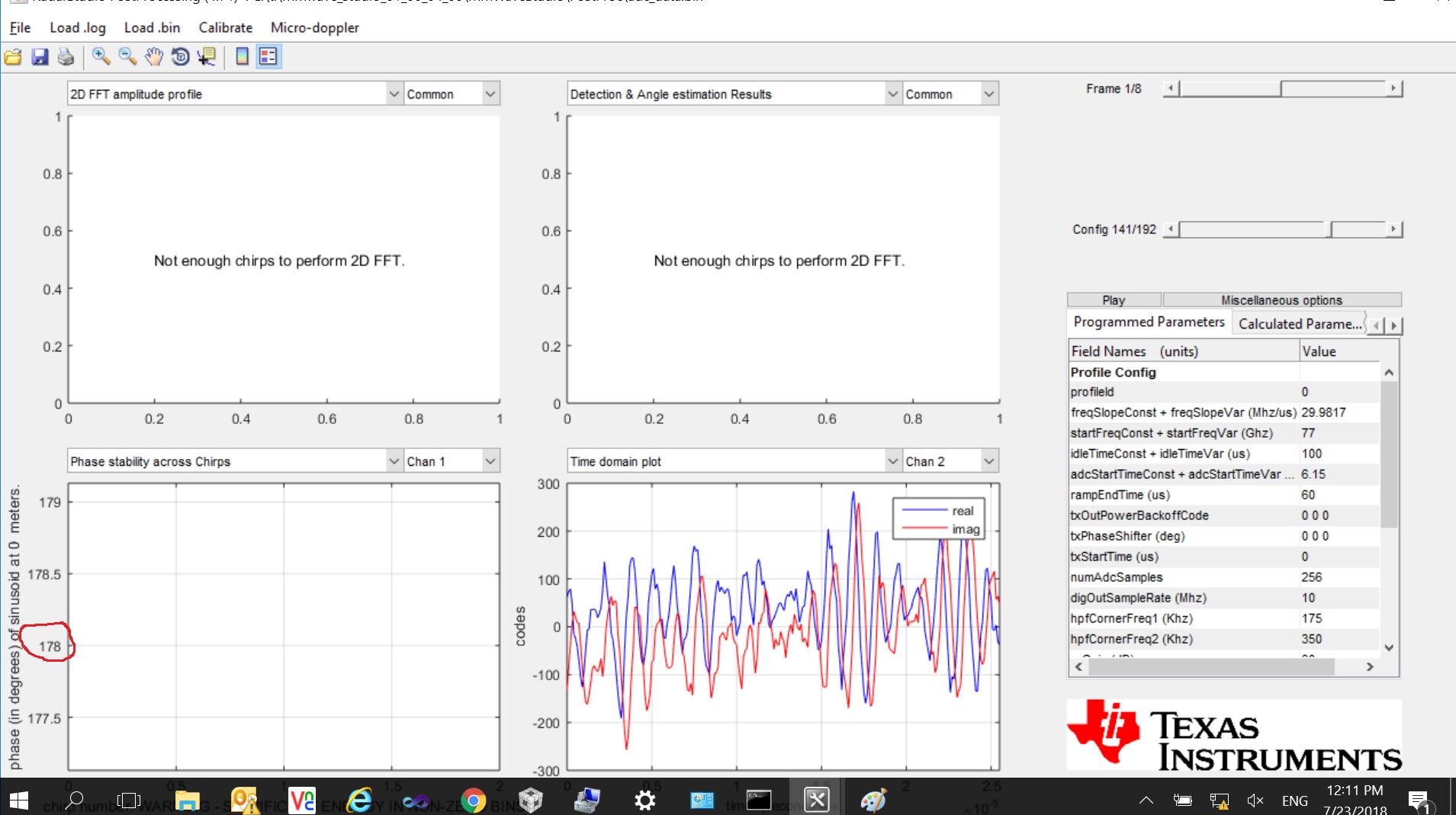
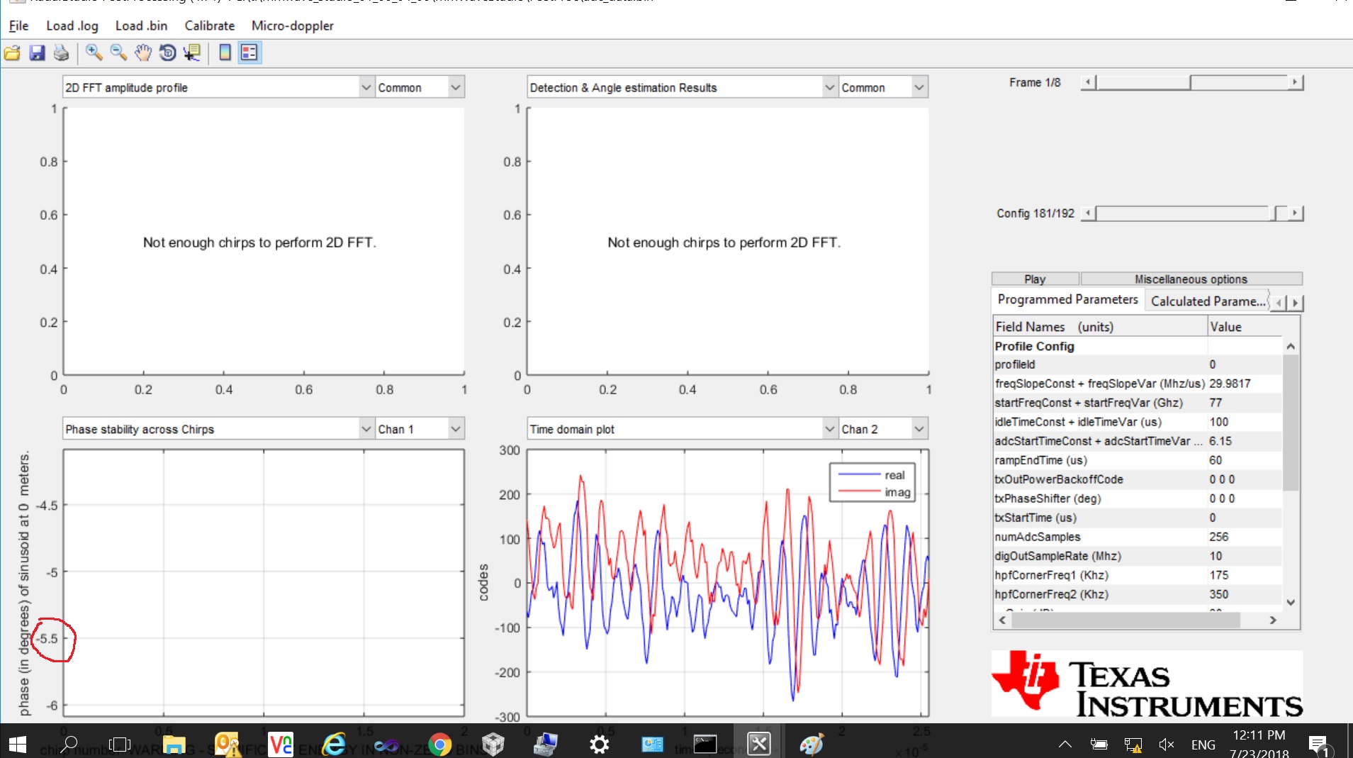
With this data I analyze the phase change after performing range FFT on it. I see an odd phenomenon as described below:

1. Most of the time, the BPM code for two Tx are proper, but for the 3rd Tx the BPM code is inverted.

2, The Tx whose BPM code is getting inverted changes every time on a Power cycle (OFF-ON). Without a power cycle, the faulty Tx remains faulty across multiple frames.

3. The Tx with inverted BPM code is not the same all the time.

4. Sometimes, rarely, we observe 2 Txs with inverted BPM code.

5. We have observed this with multiple AWR devices.

Can Anyone help us identifying the exact issue in this case?

We are strongly suspecting some kind of calibration related issue with the AWR chips. Can anyone guide us on finding the root cause of the issue.

Thanks in Advance,

Santhana Raj

  • Hi,

    I think that it would be helpful to perform some more tests.

    We are checking with our systems team to propose you some new tests

    thank you
    Cesar
  • Hi Santhana,

    I tried the similar sequence as you and it seems to work fine. See below the configuration and result.

    Please note the phase change before and after BPM code for each TX. All shows 180deg phase shift.

    Chirp 0 - 31                    TX0                    0deg

    Chirp 31 - 63                 TX0                    180deg

    Chirp 64 - 95                 TX1                    0deg

    Chirp 96 - 127               TX1                    0deg

    Chirp 128 - 159            TX2                    0deg

    Chirp 160 - 191            TX2                    180deg

    Regards,

    Kaushal

  • Hi Kaushal,

    Thank you very much for the detailed reply and the effort that you have put in. I think I was not clear in my question. Sorry, if so.

    I have also seen in Matlab analysis that there is a phase shift when I set 1/0 accordingly. I think you have also shown the same. I agree that I am also able to see the phase change of 180 deg when BPM is set to 1 and 0.

    But My question is:

    The 0 deg phase on TX0 seems to be different from the 0 deg phase on TX1 and/or TX2.

    For example, in the case that you have provided, TX0 is at 116 (0deg) and -66 (180deg) where as for TX1, it is 72 and -113 degrees.I can understand, if the 0 deg phase angle values are closer across TX, if not same. But here between Tx0 and Tx1 there is a phase difference  of around 180 deg when bpm are set to 0 in both cases.

    Hopefully you can expliain me what causes this.

  • Santhana,

    You are measuring the phase of Received Signal. Phase of transmit signal is either 0 or 180deg. Now based on the path from TX -> Object - >Rx, there would be additional phase in received signal.

    Since there is antenna spacing between TXs, there would different phase due to slightly different path.

    Also the data I provided is for RX1, If you choose different RXs, you will see again different phases due to spacing between RX antennas.

    Let us know if above answers your question.

    Regards,
    Kaushal