This thread has been locked.

If you have a related question, please click the "Ask a related question" button in the top right corner. The newly created question will be automatically linked to this question.

AWR1642BOOST: Questions on EIRP Measurement of AWR1642BOOST.

Part Number: AWR1642BOOST
Other Parts Discussed in Thread: AWR1642

I am measuring the EIRP of AWR1642BOOST.

According to the fomula of EIRP = Chip TxPower – Trace Loss + Antenna Gain.


 Assuming trace loss is about 0,

 In 1 TX, the EIRP = 12dBm – 0 + 9dBi = 21dBm.

 What I measured is very close about,

   76GHz    77GHz    78GHz    79GHz    80GHz    81GHz

   22.5dBm 23dBm   21.8dBm  22dBm   21.7dBm 20dBm


 But,

 In 2 TX, assuming the 2 antennas are equal with 2 transmitting perfect the same signal, then by calculateion, the EIRP = 15dBm (2 x 12dBm = 15dBm) – 0 + (2 x 9dBi = 12dBi) = 27dBm.

 However, my measured result is about 6~7dB higher than formula calculation as below,

   76GHz    77GHz    78GHz    79GHz    80GHz    81GHz
   34.7dBm 35.7dBm 35dBm   34.6dBm 34.1dBm 32.8dBm


 I measured in open space. Is this correct?

 Is the 2 TX antennas with 18dBi gain?


  • Jesse,

    Your analysis is correct. The EIRP with 2 TX should be 6dB higher than with a single TX. Is there any possibility that the physical setup was changed when reconfiguring to turn on the second TX to invalidate your path loss de-embedding? How are you measuring the EIRP? Is the target/receiver in the far field of AWR1642BOOST?

    Regards,
    Brian
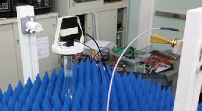
  • The test was performed with 30cm between the AWR1642 EVM and receiving horn antenna, which is supposed as far field, right?

     Please see the test setup picture attached.

    And we used the "xwr16xx_capture_demo.bin" for the test and only the chirp configuration file was modified in the "channelCfg" parameter as below:

    1TX
    flushCfg
    dfeDataOutputMode 2
    channelCfg 2 1 0
    adcCfg 2 2
    adcbufCfg 0 0 1 1
    lowPower 0 0
    contModeCfg 77 10 0 6000 0 0 30 1 1024
    setHSI LVDS ADC disable
    sensorStart
     
    2TX
    flushCfg
    dfeDataOutputMode 2
    channelCfg 2 3 0
    adcCfg 2 2
    adcbufCfg 0 0 1 1
    lowPower 0 0
    contModeCfg 77 10 0 6000 0 0 30 1 1024
    setHSI LVDS ADC disable
    sensorStart

  • Hello Jesse,
    As Brian mentioned, your analyses is correct and the increase in power should be ~6dB .
    Can you increase the distance of the receive antenna to about 1m ?

    Regards,
    Vivek
  • Thanks Vivek,

     We will check again with longer distance.

     By the way, I think the boundary between near-field and far-field definition is a little bit tricky. There are several theories about it. The most adopted formula which is  shown in wiki: https://en.wikipedia.org/wiki/Near_and_far_field .

    =====================================================================================

    =====================================================================================

     I can see that D is the largest dimension of the radiator.
     If I put 2cm as our antenna size, then the far field starts from only 20cm. But if I consider the entire AWR1642BOOST PCB as the radiator, then it should be at least 10cm square, and the far field will be start at least 5m away from the DUT.

  • Closing this thread since there was no activity for more than 7 days.

    If there are new questions please start a new thread.

    thank you
    Cesar