This thread has been locked.

If you have a related question, please click the "Ask a related question" button in the top right corner. The newly created question will be automatically linked to this question.

IWR1443BOOST: slope noise floor

Part Number: IWR1443BOOST
Other Parts Discussed in Thread: IWR1443, TIDEP-0091

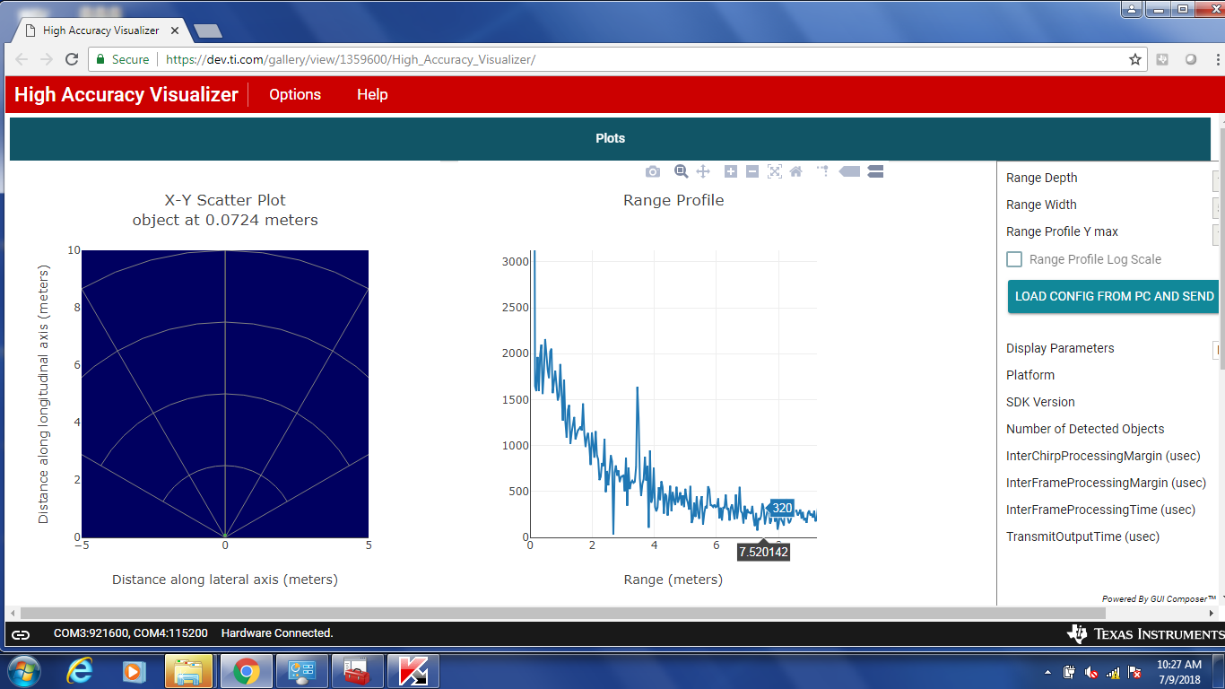
We build our own IWR1443boost boards, it is very similar to the TI's IWR1443Boost, some if the board show the "slope noise floor", any one has idea what is going on? Is this caused by IWR1443 receiver (bad chip?)?

Thanks,

  • Hello,
    Using the continuous Tx mode, I suggest you setup 4 or 6 single Tx examples, and look for spurs in the Tx. There is an example of the Continuous Tx mode discussed in the mmwave SDK User Guide. If you substituted a 40Mhz, capacitor coupled 1v sine input for CLKP no load cap, and placed a zero ohm resistor in place of the CLKM load cap, the mmwave sensor will use your external clock source.

    I would also check the 1v3 and 1v8 LDO power supply outputs with an active probe, to make sure the LDO noise output is within the Datasheet table limits.

    Please send a picture.

    Do you see the same problem on 2 boards?

    Regards,
    Joe
  • Hi Joe,

    Thanks for the answer. What do you mean 4 or 6 Tx example, do you mean 4 or 6 boards with the transmitter on only? How to look the spurs in Tx without a 80Ghz spectrum?

    Here is the waveform that I sent before:

  • Hello Feng,
    Please make you picture a PDF or JPG, I can't see it. You could also send the IQ data from the Radar cube memory.

    Trying to simplify the test, take 2 boards, and Continuous Tx, transmit on board a at 78Ghz. Check each board's output with a reference
    horn antenna, RF down converter, and spectrum analyzer. We are looking for spurs in the Tx output.

    If both boards have better than 40db SNR on Tx, set one board to Continuous Tx with an output of 78Ghz. Make sure that the first board
    is transmitting (you can measure with horn antenna above). On the second board, in the chirp configuration set the Tx to 0 (not enabled) with a profile of 77.999Ghz, Frequency slope of .001Mhz/us. Check the 2nd board Rx, you should see a chirp result that varies from 1Mhz to 1Mhz - (slope * numADCsamples_chirp / DFE output rate). You can adjust the RF coupling between the 2 boards, and check each Rx that is connected.

    Note: for the second test, you could substitute a Frequency source, Upconverter, and Horn antenna as a Tx input.

    Please make sure that unused Rx are connected to GND.

    Please check the 1.8v, 1.4v, 1.3v, and Vout_PA 1.0v, you need to meet the ripple and noise of the supplies to the mmwave sensor .

    Regards,
    Joe Quintal
  • S eems E2 cut off the waveform. Here in the attachment

  • I checked all the voltages on this board,

    1v3RF1=1.359V

    1v3RF2=1.359V

    3v3=3.247V

    1v8=1.816V

    1v2=1.211V

    2v3=2.205V

    Vbgap=0.892V

    1v4_synth=1.425V

    PA_out=0.946V

    Clkp_Fre=40MHz

    They all similar to the evaluation boards, I also change the coupling, I didn't see the slope change.

    ?????? what cause this slope?

  • Hello Feng,
    It is important to use an active probe, or use a 40Msps or higher AC coupled oscilloscope measurement, we need to make sure the power supply noise is not coupling into the Radar Rx.

    You can tell me what you setup is, so this can be measured, or you can measure this comparing to the EVM.
    The data capture demo, in later mmwave SDK under the drivers, you can capture the radar cube memory.
    Regards,
    Joe Quintal
  • Hi Joe,
    I use 100MHz oscilloscope with AC coupling, the 40MHz signal are very clean. All the power supply signal meet the hardware requirement which less then 2.5% of the target voltage. If I use Tx1 and Rx4, what should I configure in channelcfg?

    Thanks,
  • Hello
    The oscilloscope measurements are for both the 40Mhz crystal, which you have done, and to measure the ripple and noise 1.3v, 1.8v in the datasheet.
    You should also measure the noise and ripple of the 1.4v outputs, and the RF_PA 1.0v output.
    You can compare your measurements to the EVM board you have.

    Tx1 is 0x1, Rx4 is 0x8 - these are bit fields. Please see section 3.4 in the mmwave SDK User Guide.

    Unused Rx inputs should be tied to GND.

    Regards,
    Joe Quintal
  • Hello Feng,
    The slope is indicating you get an Rx reflection close to the Tx and Rx , the frame-configuration-chirp is not correct, the radar power supply is noisy (AC ripple and noise comparison measurements to EVM), or possibly that the BSS and MSS software needed should use the latest version of the mmwave SDK compatible with your device. Current released part for IWr1443 ES2, mmwave_sdk_01_02_00_05.
    Note: lower power - level sensing TIDEP-0091 will be re-released this quarter.
    Regards,
    Joe Quintal
  • Hi Joe,

    Thanks for the continuous support! Let us close this thread.