This thread has been locked.

If you have a related question, please click the "Ask a related question" button in the top right corner. The newly created question will be automatically linked to this question.

AWR1642: Hardware issues with AWR1642

Part Number: AWR1642

Hello, I have a few questions that need your help.

1. The PMIC chip itself can output the voltage required by the AWR1642. Why add an LDO chip in the middle?

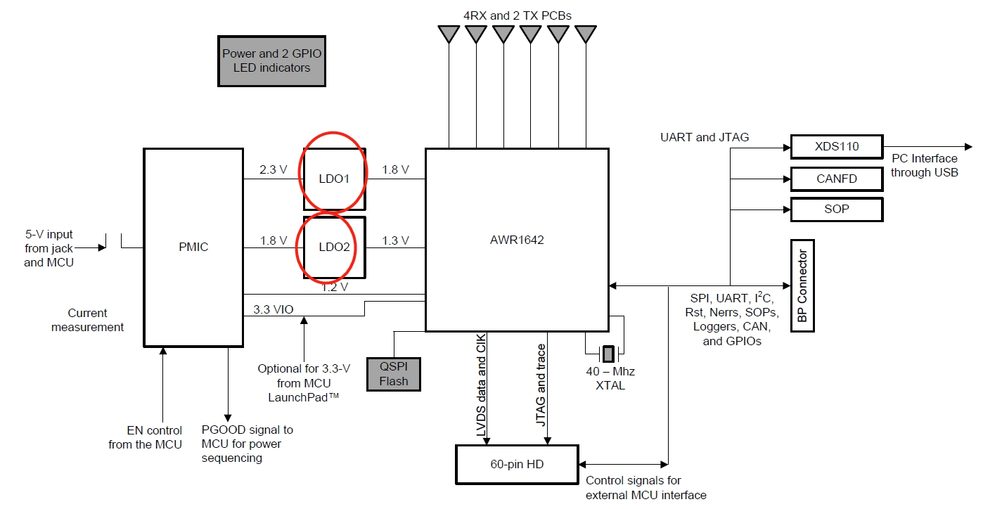
2. What is the load current of 1.8V, 1.3V, 1.3V, and 3.3V of the AWR1642?

3. What is the maximum capacity of QSPI Flash?

4. We use the AWR1642 to do heartbeat monitoring and obstacle avoidance wheelchairs. Can the power supply be implemented with a discrete BUCK step-down circuit? Or use other similar PMIC chips instead?

Thanks~

  • Hello,

    1. The LDO's were added for additional stability. The 1.8V and 1.3V supplies are very sensitive to ripple. In order to maximize RF performance the ripple should be kept to a minimum, as shown by the specifications in Table 5-2 of the datasheet.

    2. You can find the power consumption summary in Table 5-3 of the datasheet.

    3. The capacity of the QSPI flash module on the EVM is 32Mbit.

    4. We recommend only using power schemes used in our reference designs due to the RF sensitivity to ripple. Power supply schemes in our reference designs have been tested and proven to provide the expected RF performance. You can also look at TIDA01570 for an additional power scheme.

    Regards,

    Adrian