This thread has been locked.

If you have a related question, please click the "Ask a related question" button in the top right corner. The newly created question will be automatically linked to this question.

AWR1243: Programming Serial Data Flash Over UART

Part Number: AWR1243
Other Parts Discussed in Thread: UNIFLASH, , TPS7A8101, TPS74801,

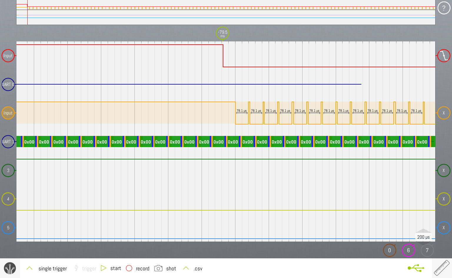
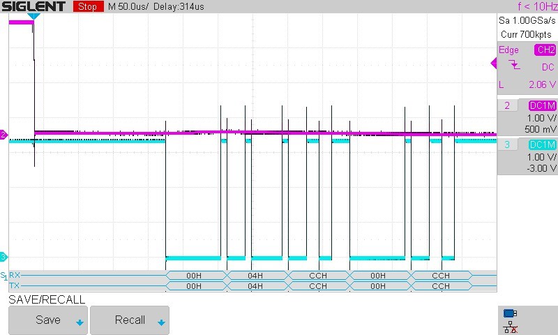
I am seeing the same response from the radio that Daisuke was getting on his customer's board.  When Uniflash sends the UART break message, the AWR1243 responds with a never-ending stream of "00" (with proper start and stop bits).

This is my own custom AWR1243 Cascade board, but I am getting the same response from all 4 radios after changing the clock structure to feed 40MHz to all radios directly.  The design is directly copied in most part from the TI Boost and Cascade designs.

The SOP jumpers are properly reading "101".  I was also concerned that my flash may be incorrect, but upon probing, the AWR1243 isn't even trying to hit the flash.  In fact, it is pulling CS low continuously.

All of the radio power rails appear to be correct.  I am using an external LDO for the 1.0V instead of the internal to reduce the heat in the radios.  VBGAP measures 0.82V.

I am running out of ideas on what to check next.  I have the Boost board and am comparing each signal on my board to it.  No luck as of yet.

Thanks for any suggestions on what to try next.

Darin

  • Hi

    In our concept cascade boards we use mmwave studio to flash the boatrds through SPI.

    We need to check with our hw team and get back to you early next week

    Thank you
    Cesar
  • Thank you for your prompt response Cesar.

    The Master radio in the cascade design shouldn't be different than the radio on the Boost board.  I'm not even attempting to load the firmware yet.  I can't get past the format step. Are mmWave Studio and Radar Studio the same?  My understanding was that UART is needed to erase and program the QSPI flash before SPI is enabled.

    Daisuke-san's customer was seeing the same response on his board, and I didn't get the impression that it was cascade.  I don't see his post linked here as a related question as I expected.  One difference is that I am using an FT232RQ chip on the board instead of the microcontroller on the Boost board.  I don't see the MCU doing anything with its AR_NRST_XDS line, so I thought the FT chip would be a better option.  Uniflash is leaving plenty of time, so I don't think baud rate is the issue.  The fact that the AWR1243 isn't attempting to access the flash at all, and is even driving CS low, tells me that it isn't an issue with my selection of flash device.

    I look forward to hearing back from the HW team on why the radio might respond in this strange fashion. Any clues on where to look next would be much appreciated.  Thanks again.

    Darin

  • Hello Darin,
    Could you provide the error you are getting in the Uniflash during this flashing?
    You mentioned that the SOP jumpers are set to 1 0 1, have you made sure the voltage level on the AWR SOP pins is indeed 3.3V - 0V - 3.3V by keeping the AWR device in reset? Once the SOP lines are configured only then should the nRST of the AWR device be released. Also make sure there is no other source driving the SOP line voltages.

    Regards,
    Vivek
  • Vivek,

    I have checked the SOP lines.  There were some issues, but I have resolved those.  It also appeared that NRST might be glitching.  I only had the 47.5K pullup on those lines, so I added another 10K pullup to each.

    I am seeing 3.1V - 0.0V - 3.2V at the radio itself while holding down NRST.  I have confirmed that these are still stable when NRST goes high again.  Could a wrong setting of the SOPs cause a crazy response like that to just the RS232_RX pin going low?  Pin N5 is the input, correct?

    Here is the screenshot of Uniflash locking up when the radio responds with all "00".  Also a shot of Device Manager showing COM11.  I am using a standard FT232RQ bridge driver, not the XDS110 used on the BOOST board.  Is this a problem?  It should just be a COM port, right?  Uniflash doesn't give options for Baud rate.  The scope shows it is 115,200 even though I set 9,600 in Device Manager.  Shouldn't matter since the TX is just driving low when this all goes down.

    Still trying to find it.  Would appreciate any more good ideas on where to look.  Thanks.

    Darin

  • Hello Darin,
    Yes you can use an external FTDI, its just a COM port as you indicated.
    Pin N5 is input to the AWr device. If the SOP mode is not set correctly the chip will not send the break sequence.
    In the above scope capture can you highlight which channels correspond to which signals?

    Regards,
    Dham
  • Dham,

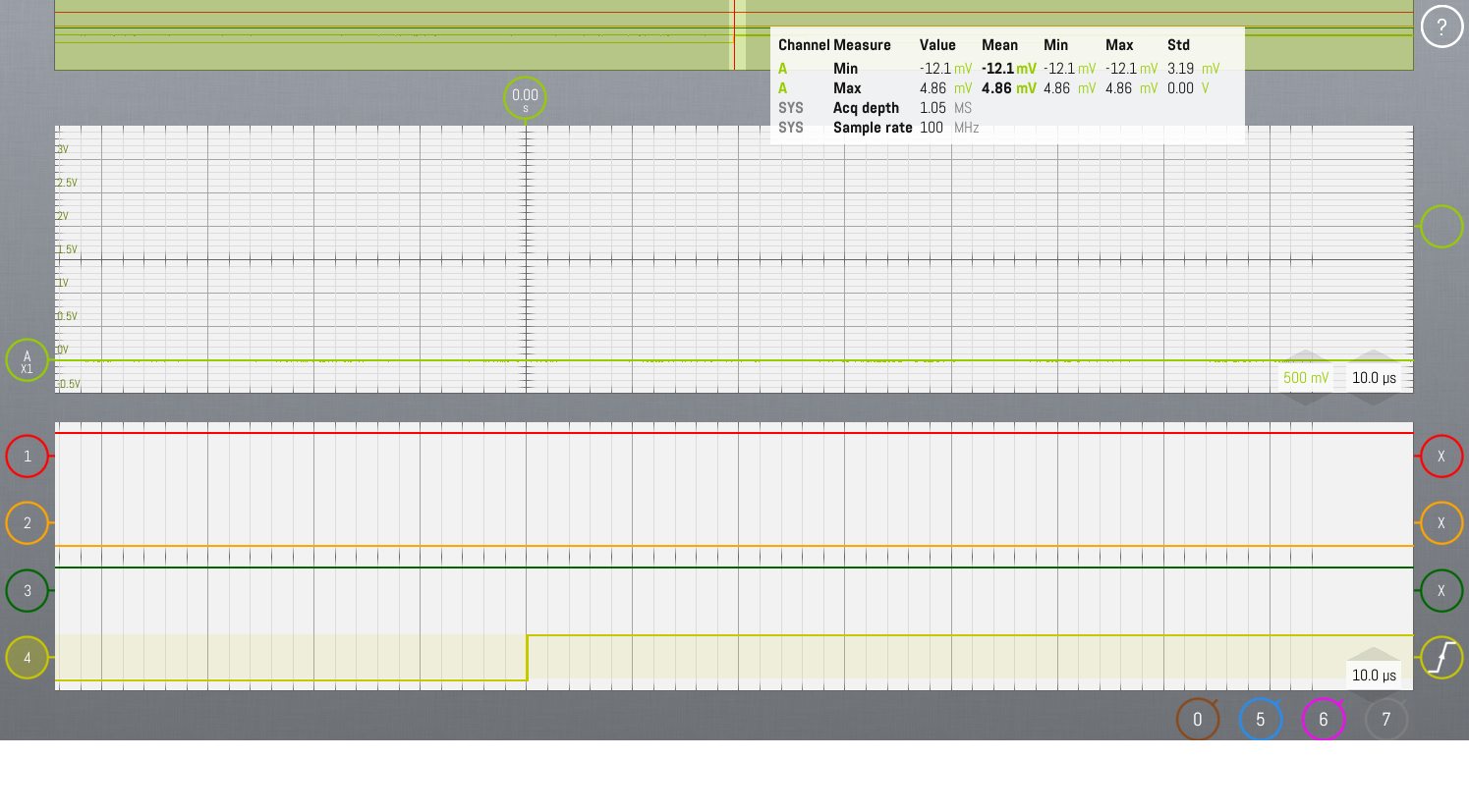
    The scope won't let me label the channels, so I put them in order in the file name.  If you click on the picture you can see the file name.  Ignore the analog trace.  On the digital, from top to bottom:

    SOP2, SOP1, SOP0, NRST.

    So you see that the pattern is 1-0-1 long before NRST goes high.

    The response from the radio should be an ACK (00-04-CC-00-CC) as I am seeing on the Boost board.  One concern that I have is that the NRST line is glitching on the falling edge of RX (Stop bit of the first "00"), causing the radio to start the sequence over again and again.  I am ordering a much faster scope to try to catch it.  I would expect it to occasionally make it to the "04" in this case though.  In 100 "00"'s, I see no "04", so probably not the problem.

    I am also looking into the power-up sequence of the radio.  There is no CPU holding the radio in reset, and I see it is coming out prior to the clock.  The Boost board has a 10K/0.1uF ramp, and I assume that the Cascade digital board processor probably holds it in reset.  To alleviate this possbility, I held NRST down for a second during power-up - still got the stream of "00".  I'll be checking the order of the supplies next.

    So you are saying that the radio won't respond at all if the SOP lines were incorrect, not respond with "00"'s?  I just set SOP to 0-0-1 with the same response from the radio, then 0-1-1, again with the same response (power-cycling after changing the switches).  An incorrect code still gives me the bad response, and I think that I already proved to myself that I am set to 1-0-1.

    I am ordering a much faster 4-ch scope, so I will continue to look for instability in the supplies or clocks.  Are there any undocumented other bootstraps, like the pullups and pulldowns on the various signals?  I think that I have them correct, but there are a couple of very minor differences between the Boost schematic and the Cascade schematic (like 100K pullup on RS232_TX).  I sent a request to Dan for a list of redlines to the Cascade schematic prior to my going to fab, but was referred to your BU manager Sneha.  The schematic that I have is rev 1.7, so she likely caught most of the mistakes in those 7 sub-revisions.  I have been doing this for 25 years, so I know that process all too well.

    Any new ideas to test while I wait for the 2.5GHz scope?  Thanks for your help.  It looks like you responded just a couple of hours after I gave up last night and went to bed.

    Darin

  • Dham,

    Should there be a voltage on VOUT_14APLL1 or VOUT_14SYNTH before the firmware is loaded?  I'm not seeing anything.  VOUT_PA is 1.0V because I have it connected to the same LDO as AR_1V_RF as is done on the Cascade board.  The Boost board doesn't have that connection stuffed, but I'm guessing this has something to do with bypassing the internal LDO.  VBGAP comes up to ~0.88V just after NRST is released.  VBGAP is top trace and NRST is bottom.

  • Hello Darmin,
    The VOUT_14APLL1 should have come upto 1.4V once you release the reset in SOP mode 5 (1 0 1). Could there be some issue with the power supply?

    Regards,
    Vivek
  • Vivek,

    From which power supply is AR_1V4_APLL derived? They are all there.
    I added the 0.1uF to the NRST lines, but the extra 1ms didn't help.

    - It looks like I am seeing 1.43V on the APLL line today.  May have just been a bad connection yesterday.  I shorted SOP lines directly to 3.3- 0 - 3.3V to leave no doubt, but then APLL was still there when I disconnected them and cycled power.  I did confirm on the Boost board that some SOP settings result in APLL not coming up, but mine appears to be okay.  Sorry for the false alarm.  I will keep an eye on it. 

    Darin

  • Vivek,

    I found that 5 of the 8 possible combinations of SOP on the Boost board will result in the behavior that I am seeing.  

    Here is the output of the RS232_TX based on the SOP settings on the TI AWR1243 Boost board:

    SOP2  SOP1  SOP0

    0 - No output

    1 - All "00"s stream

    2 - TX and RX both come up pulled low

    3 - All "00"s stream

    4 - All "00"s stream

    5 - Correct ACK respone

    6 - All "00"s stream

    7 - All "00"s stream

    But I physically have the 3 SOP lines shorted to 3.3V - 0V - 3.3V.  I traced these SOP lines back to the pins of the BGA (P13, P11, J13) on the BRD files for my board and the Boost board.  On power-up, I shorted NRST to GND for a second until it is certain that all of the supplies are stable, then released it.  This was easier immediately than wire-ORing all of the PGOOD signals.  Yet, still, the RS232_RX (TX pin on the AWR1243) sputters out "00"s right after the TX is pulled low.  I'm not even using software to drive TX low anymore.  I am physically shorting it to GND.  The RS232_TX of the radio has been isolated from the RS232_RX of the UART chip to avoid interactions.  The Radio is the culprit in the screwy response.

    I have been going back and forth between the Boost and my board, checking voltages, parts, and layout differences.  Changing where I am able to, it still isn't helping.  I'm on day 16 and running out of time and options.

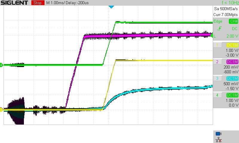
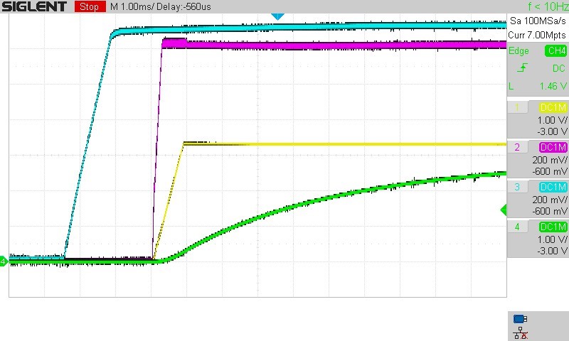
    The Boost board uses a TPS7A8101 LDO for the radio 1.8V.  The Cascade design changed this to a TPS74801, which I followed.  The 74801 requires 3.3V to be there as a bias, so even though 2.3V is the first supply up on the PMIC, 1V8 is the last to come up at the radio.  On top of that, it ramps really slowly with a 10nF softstart cap.  The blue trace below is the AR_1V8 just starting to ramp up after 3.3V (yellow trace) is up.  Green is the NRST line.

    In theory, the radio only cares about NRST being held until all supplies are up.  I have tried that with no success.  Next, I will try to get some of the TPS7A8101 LDOs and deadbug it in.

    What more can be done?  We have an NDA in place.  If I sent the schematic to you, is there anybody there with the qualifications and time to look it over?

    Darin

  • Vivek,
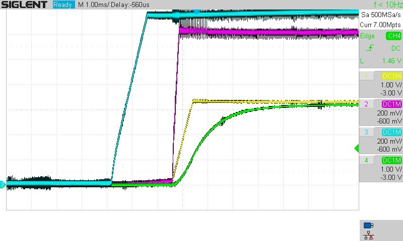
    It turned out that the TPS7A8101 on Boost has an unstated softstart cap too, so it comes up just as slow. By removing the SS cap on my 1.8V LDO, that rail comes up quickly at the same time as the 3V3 bias. Adding the 0.1uF cap to the NRST line, all of the rails are now up before reset (though not by the 3ms required). I see that 1V4_APLL doesn't go high until I toggle NRST again, so that could be a clue. Only if 1V4_APLL is 1.4V does the UARTRX (TX from the radio) have the 00's response. Otherwise, no response at all.
    I tried 1-1-0, 1-0-1, and 0-1-1 on the SOP pins in case I had them out of order. They responded the same as on the Boost board described above (except 00's instead of ACK for 1-0-1). Trying 0-1-0 caused RX and TX to be pulled low, just like on the Boost board. So I think that I have all of those correct.
    Still searching for an answer.
    Darin
  • Hello Darin,
    Now that we established that the device is powering up and the 1V4_APLL is coming up properly (with toggling nRST) lets come back to the UART communication.

    My understanding is that the uniflash is getting stuck after "set break signal" , is that right?

    Lets use the fixed nomenclature for communication between RX and Tx so that there is no confusion -
    UART_RX (AWR pin N5) - This is input to the AWR and should be connected to the UART TX pin of the FT232
    UART_TX (AWR pin N6) - This is output from the AWR and should be connected to the UART RX pin of the FT232

    Now, the step is that the AWR device should receive a break signal on the UART_RX line when you try to flash from uniflash. Is that coming? Can you share the snapshots of the UART_RX and UART_TX lines from your board and AWR1243BOOST? From the plots you have shared above the labeling etc. is a little confusing and I am not sure which label corresponds to which signal and is taken on which board.

    BTW, can you confirm if the device you have is AWR1243 ES3.0 ? Also what is the application you are trying to flash?

    Regards,
    Vivek
  • Hi Vivek,

    Yes, Uniflash is getting stuck after "set break" signal.  I found with the scope that Uniflash is indeed sending the "set break" signal.  Digging deeper, I am able to establish the same response by simple shorting UART RX to ground and looking at UART TX.  This saves me a bunch of time since Uniflash has to be closed and the task ended in Task Manager every time.  Doing the "set break" function from RealTerm also has this response.

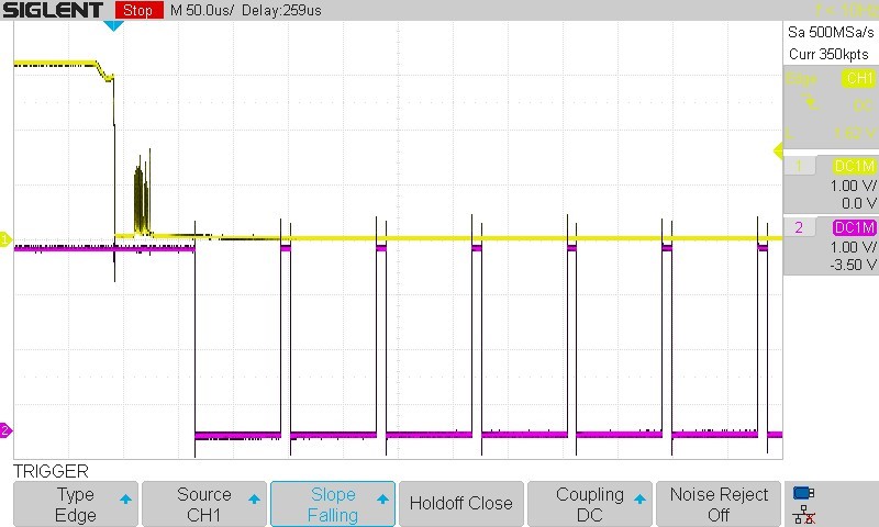
    Here are the scope captures of our board and the Boost board, respectively.  The top trace is UART_RX being pulled low, and the bottom trace is the UART_TX response from the AWR1243.

    I had a concern that shorting SOP lines directly to 3.3V - 0V - 3.3V might be doing something wrong, but I confirmed last night (in the trace above) that the Boost board responds fine with that as well.

    I sketched out the circuits for the 3 SOP lines, both for the Boost and for my board.  With the DevPack disconnected, and ignoring the fact that I drive them more directly than the Boost 7.87K/82.5K voltage divider (verified okay in last paragraph), there are two things that I do differently.  The AR_SYNC_OUT_SOP1 line also feeds into the CDCV3D4 clock buffer from your Cascade board design, and I have the AR_PMIC_CLKOUT_SOP2 line connected to the clock input of the PMIC per your Cascade reference design.  My next step is to try these, though they should both just be inputs and not make any difference.  Assuming your rev. 1.7 schematic of the Cascade was correct, you have also verified this circuit. 

    Unfortunately, my board is at the rework house.  I shorted something on one radio when probing and couldn't even get the bad response, so I moved on to another radio for debug.  Tuesday evening, I shorted a PMIC output and brought the whole board down, so I am having both chips replaced.  Back tomorrow morning.

    I purchased these parts from your site March 28th.  Part number was X1243BIGABL.  I believe that we established that 3.0 silicon wasn't released, but it was late enough that it should be 2.0.  I don't have the chips in front of me anymore to verify the "D", but I can tomorrow, or contact my co-worker who has the second board.  It looks like 134 pcs recently showed up for sale on the TI store.  Are these now all rev 3.0 silicon?  Do you think it is worth putting my rework on hold and rushing one of these parts for my board?  I don't see anything in the errata that remotely points to this problem.

    Adding your 10K pullup/ 0.1uF cap to my NRST line, the power-up sequence looks remarkably similar to the Boost board.  Our board is first.  Left to right are 1P3_RF, 1V2, 3V3, NRST. 

    So, the power-up is almost identical and the SOP lines are literally shorted to their rails.  I'll need to confirm again when the board comes back, but I believe that I had to toggle NRST again after power-up to get AR_1V4_APLL to come up on my board.  This isn't necessary on the Boost board.  That has gotta be a clue, but I haven't figure out what.  There are slight differences in layout between the boards because we copied our layout exactly from the TI Cascade board.  Most notably, we use the digital and FMCW Syncout and Syncin lines to connect the chips.  I can try disconnecting all of those temporarily to see if it makes any difference.  Again, this is what you have on your Cascade reference board, so it should be good.

    I'm still thinking of things to try every day, but nothing is changing the outcome.  Any other ideas?

    Darin

  • Hello Darin,
    Do you have a serial flash connected to the AWr device? If so can you let us know the part number of the flash?

    Regards,
    Vivek
  • Hello Vivek,

    Yes, the part number for my SPI flash is S25FL064LABNFI011.  This is the part that Spansion/Cypress recommends as the replacement for the now obsolete S25FL116K0XNFV010 on the Boost board.  There is an upgrade path document on their site listing the register differences.  I did initially consider this as a potential issue.

    But, as I mentioned in a previous post, I monitored the CS and CLK lines to the flash.  CS is constant low and there is no clock.  Unless your list of acceptable flash is in silicon, it seems no way it could know that it is the wrong flash before the UART programs something anyway.  I would assume it uses the Common Flash Interface instruction set until firmware is loaded.

    Darin

  • Hello Darin,
    You are right , this does not seem to be a serial flash related issue.
    There seems to a "disturbance" on the UART RX line some time after its pulled low. Is that consistently seen? For detecting a break sequence the UART RX should be low for >8 clock cycles. You can see that in your capture on the TI EVM the break is held low for a longer period. Could it be that the "disturbance" be falsely been detected as high?
    Also can you make sure the FTDI device you are using is operating at 115200 kbps ?

    Could you let us know if the JTAG interface is available on your board, and incase we need to connect that would it be possible?

    Regards,
    Vivek
  • I'm sorry Vivek.  No, that disturbance isn't consistent.  I should have sent you a better capture.  At this point, I'm just shorting RX to GND to simulate the break sequence.  That's why you see the glitch.  The response is the same regardless of how I instigate it.

    I switched back to trying Radar Studio instead of Uniflash.  The FTDI chip is definitely set up correctly because RS connects and even tries to program the flash.  I see it send the same commands as the Boost (at the same rate), but the radio just echos back the commands.  Comparing against the boost board, after connecting RS232, the status is different.  Boost shows "XWR1243\ASIL-B\SOP:2" whereas my board shows "XWR1243\ASIL-B\SOP:Inv".  What does SOP:Inv mean?  Is this an invalid SOP?

    I see that I2C writes and reads addresses 0x48, 0x49, 0x4A, and 0x4B right as it is coming up.  The first 2 are the temp sensors on the Boost board.  Are the second on some other board, so Radar Studio is using this to identify the board?  I don't have I2C connected on the FT4232HQ as it was indicated that it wasn't used, but I do have access to the pins to connect it if needed.

    Likewise, I didn't bring JTAG on the radios out to headers to simplify routing and space.  I did leave test pads so I can rework something up if need be.

  • Hello Darin,
    That is good clue. The SOP:Inv means the SOP mode is not getting set properly. If the SOP lines are detected properly as 0 1 1 [ SOP2 SOP1 SOP0] then it should have read SOP 2. Could you double check the SOP line drive and connections? Maybe you can send the schematic portion of the SOP lines and how you are driving them?

    Not connecting I2C is not an issue, that is not mandatory.

    Regards,
    Vivek
  • Vivek,

    Thank you for your feedback.  I have resolved the issue with the SOP:Inv problem.  The SOP lines going to my FT4232 USB bridge were 1 pin off from the DevPack, so the Set SOP Mode function in Radar Studio was setting the wrong Mode.  With that fixed, I am able to download the BSS and MSS firmware to the radio.  My colleague has gotten to this same point with his software on the TDA2Px platform. This is bypassing the SPI flash though, so we still don't have a way to get our code in there.  For now, we will push forward using the SPI FW download.

    The original issue is still there.  I wasn't using the FT4232 or my switches on my adapter board to set the SOP.  For much of my experiments, I was just tying SOP0 and SOP2 to 3.3V and tying SOP1 to GND.

    Now that I have Radar Studio able to set the SOP Mode for sure, though, I ran another experiment.  First, I used RS to Set SOP Mode 5.  I then did an RS232 connect and verified that status was SOP5.  Good.

    After resetting and power-cycling everything, I used RS to Set SOP Mode 5, but then opened Uniflash.  Now that SOP is confirmed to be 5, I attempted a Format Flash.  I get the same repeating series of "00"'s and a wedged Uniflash.

    So, while I do believe that we resolved the problem of Radar Studio setting an invalid SOP, the radio is still responding improperly to a UART break signal.  We can work around it uploading firmware through SPI for now, but the problem hasn't gone away.  Maybe it will just be moot when you release chips with the firmware installed.

    I don't know what to try next on the original problem.  It would be great to resolve it for anybody else running into it.  Since the Boost board works, I obviously have done something enough different from TI to cause the problem.  It may remain a mystery.

    Darin

  • This issue isn't really resolved, but I'm going to close it since I can't think of anything else to try.  I'll move on to the next issue.  Thanks for all of your suggestions Vivek.