A related question is a question created from another question. When the related question is created, it will be automatically linked to the original question.
If you have a related question, please click the "Ask a related question" button in the top right corner. The newly created question will be automatically linked to this question.
i'm sorry post wrong forum, but the Automotive only read. so, anyone can help me? thanks!
1、PGA450-Q work with external cystal clock 16MHz . I modified CLK_SEL = 0b10 in the initial code of OTP memory.
2、communication with uart . send command 1 and the board can return the first instance for closest object detected. then send command 4, get all 768 bytes of FIFO data that contain echo waveform(not zero values).
3、I turn off power, and power up again . repeat step 2 operation again , the board can not return the first instance ,it detected nothing ,and the FIFO read as zero. ( The sensor is good and can vibrate).
4、Repeat step 3 again, It worked again ,can detected object and return the echo waveform . In my tests, Sometimes it work, sometimes it don't work ,
5、modify CLK_SEL to 0b00 in the initial code of OTP memory for internal clock , and put the cystal clock off ,and programming a new device OTP memory. then the new one work good .
You are posting in the correct forum. The PGA450-Q1 and PGA460-Q1 products are now supported in the Ultrasonic Sensing forum.
When using an external clock, you have correctly set the CLK_SEL register to = 0b10 according to the CLK_SELx Bit Configurations.
The PGA450-Q1 implements an internal free-running 500-kHz watchdog clock. This watchdog clock is used to monitor the internal 16-MHz main oscillator or the external crystal oscillator. When this frequency is outside this range, an internal reset is generated, which resets the entire digital core; this is equivalent to POR. The main oscillator frequency fail limits have the following ranges as shown in Figure 44 of the datasheet.
Try disabling the main oscillator watchdog using the OSC_WD_EN bit in the WD_EN register, and then repeat steps 1-3. Do you have the same zero-return issue? Note: A reset because of main oscillator watchdog failure causes an internal digital core reset. All ESFRs revert back to the reset sate.
If this doesn't work, also try disabling the Software Watchdog.
Can you use an oscilloscope to confirm whether the external crystal is actually at 16MHz +/-2MHz?
I use <PGA450Q1EVM-S UART Demo V2.6 >code. It doesn't use WD_EN bit , Both OSC_WD_EN and SW_WD_EN are not set.
But, I added a code "WD_EN = WD_EN & 0xFE" at first line of initialization() still , programming and test , Get the same zero-return issue sometimes .
The software watchdog can be disabled using the SW_WD_EN bit in the WD_EN register. The following lists thebehavior of this bit: • The SW_WD_EN bit is in the disabled state after power-on reset (POR).
So didn't try close SW_WD_EN because this bit shoutdown default. Did I do it right?
I confirmed the external crystal use oscilloscope , at 16 + 0.16Mhz. when the issue ocuured or not ocuured.
On other hand, I tried to replace the external crystal with another production , It works good, I tried four chips ,worked good too . but how make it happen?
I sould pay attention to Load Capacitance or Operation Temperature Range of crystal ?
Sorry for not responding to your original follow-up question. To clarify your last comments: After replacing the external crystal, the issue was resolved? If so, what is the part number of the external crystal you are using? How many units are failing vs passing?
I will re-investigate this oscillator issue, and attempt to replicate the failure using an external crystal oscillator with the EVM.
Another variable to consider in the event of faulty code execution is the VPWR ramp rate as discussed in the following AppNote:
Thanks your reply. So,After replacing the external crystal , the issue can resolved. not saw in tests at least.
By now, Two out of every 1,000 products may have this issue . external crystal of EPSON part number : TSX-3225 16.0MHz 12.0pf +10.0-10.0
Yes , our board's VPWR had the Reset Issue,and hasn't improved.
Now ,describe the crystal issue of the faulty products :
1、Use the 12DC power button , to control board power on and power off,
2、First power off , pause about 1s to ensure full discharge,then power on to work and read FIFO ; Let's call this process "OneBoot"
3、We tested 20 times of "OneBoot", 1~2 times zero-return issue in 30 times test.
4、this issue is very difficult to detection and filtrate it out. Show instability , I guess pessimistically, maybe 2 or 5 days later It will read zero all time.
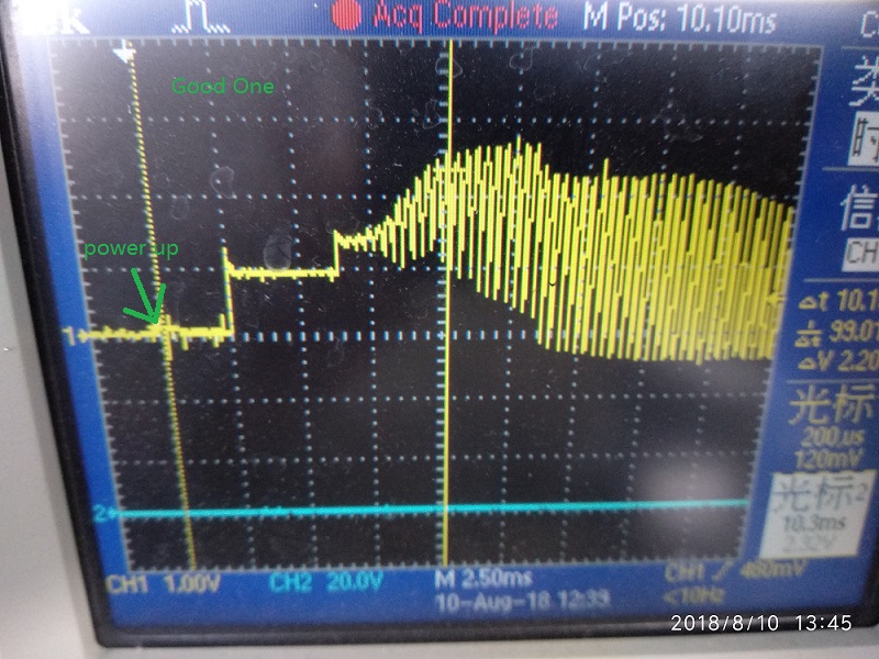
1. When the issue occurs, is the external crystal oscillator fully powered? Are you able to capture an oscilloscope output of the crystal oscillator during power-up for both good and bad initialization cases, and when attempting to UART-communicate with the device.
2. When the issue has occurred, are you able to send Cmd1 to excite the transducer, but unable to read back the FIFO results through Cmd4? We are trying to determine if only transmit commands are working, but not receive commands.
3. How long do you wait after power-up before attempting to UART-communicate with the device? Are you waiting at least 10ms?
1、When the issue occurs, is the external crystal oscillator fully powered? yes! it working.
just two picture of the crystal oscillator during power-up. other one, sorry have no picture, but I watched, the crystal haven't changed when attempting to UART-communicate with the device.
The oscilloscope does not show the completed 16M waveform. It‘s not good at capturing 16MHz waves.
2、When the issue has occurred, are you able to send Cmd1 to excite the transducer, but unable to read back the FIFO results through Cmd4? We are trying to determine if only transmit commands are working, but not receive commands.
When the issue has occurred, Cmd1 can excite the transducer, I touched the transducer and felt vibration. And Cmd4 can read back the FIFO's bytes, but they are 0x00 all.
3、How long do you wait after power-up before attempting to UART-communicate with the device? Are you waiting at least 10ms?
waited at least 100ms after power-up .
Other hand , When 12Vdc power off ,Only UART-communicate IOs still have 3.3V through the UART interface pull-up resistor.
I have a new set of questions:
1) Can you provide an example of the raw UART transmit commands of CMD1 and CMD4 from your master controller?
2) Can you provide an oscilloscope screen capture of the UART-RX for an incoming CMD4 in the good and bad cases? (CSV output preferred)
3) Can you provide the schematic of your PGA450-Q1 solution and the UART interface to your master controller.
4) When you say you are only reading back 0x00 values from CMD4, is the device actually sending back 768 bytes of 0x00 (with the UART start and stop bits), or does the device not appear to respond at all, such that the UART-TX pin is always low after sending CMD4? If the device is actually returning 768 bytes of FIFO data, but it is 0x00, there may be an issue with the FIFO Enable state in the bad case.
Please send your reply in a private E2E message to move this discussion offline from the public forum.
2) Can you provide an oscilloscope screen capture of the UART-RX for an incoming CMD4 in the good and bad cases? (CSV output preferred)
Need time ....
3) Can you provide the schematic of your PGA450-Q1 solution and the UART interface to your master controller.
Can you agree to my friend request.... sending private message need friendship in E2E?
4) When you say you are only reading back 0x00 values from CMD4, is the device actually sending back 768 bytes of 0x00 (with the UART start and stop bits), or does the device not appear to respond at all, such that the UART-TX pin is always low after sending CMD4?
I check the data on computer and oscilloscope , Device actually send back 768 bytes of 0x00( whith the UART start and stop bits). And it worked with command1 and command4.
Given the device is returning 768 bytes of data, this confirms that the device is correctly receiving your commands, and responding accordingly. However, if all 768 FIFO bytes are zero, this may indicate that the FIFO is not filling because ECHO_EN=0 (0: Disable echo processing – the FIFO is not filled. 1: Enable echo processing – the FIFO starts filling after the blanking timer expires.)
Can you add the ability to check the value of ECHO_EN just before every burst/listen command?
After doing so, is ECHO_EN=0 when all of the FIFO is 0?
You have already confirmed that the device is bursting even when all of the FIFO is 0, so I currently suspect the device is not filling the FIFO in this fail state.
I got 60K points data of "cmd4 back" from oscilloscope , save by csv ;all 768 FIFO bytes are zero. but this forum dose not support sending to you.
Other hand , i don't think ECHO_EN =0 when device working by command1, if so, the program will not run :
code: for(lcv=thrIgnore;lcv<767;lcv++)
{
// Read FIFO Pointer coherently
while ( lcv >= FifoWritePointer.u16 )
{
FifoWritePointer.u8[0] = FIFO_POINTER_MSB;
FifoWritePointer.u8[1] = FIFO_POINTER_LSB;
if ( FifoWritePointer.u8[0] != FIFO_POINTER_MSB ) // Check if coherent
{
FifoWritePointer.u8[0] = FIFO_POINTER_MSB;
FifoWritePointer.u8[1] = FIFO_POINTER_LSB;
}
}
......
}
No filling No pointer value increasesing , can not break and no back data .
However, the FIFO memory contents are not cleared to 0 ,when power up or ECHO_EN =1; ( datasheet page 42.)