This thread has been locked.

If you have a related question, please click the "Ask a related question" button in the top right corner. The newly created question will be automatically linked to this question.

AWR1642: question about lane format 0/1 in mmwave studio

Part Number: AWR1642
Other Parts Discussed in Thread: AWR1243, AWR1443

fig1

fig2

i am using AWR1642+TSW1400 to capture ADC data.

1/ in mmwave studio (see fig 2), format 0 means adc_data.bin from tsw1400 is interleaved and format 1 means adc_data.bin from tsw1400 is non-interleaved?

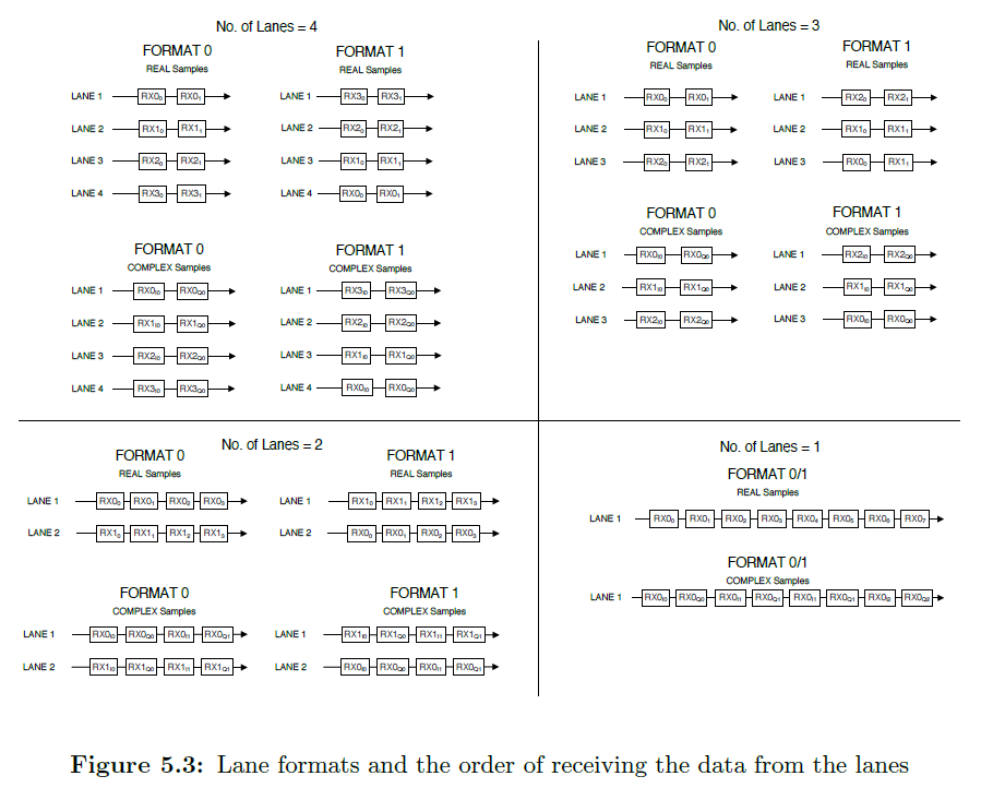
2/ also i read skd user guide (Product Release 1.0.0,Release Date: May 2, 2017,Document Version: 1.0).

i see the requirement of awr1642 on page 20.

does it mean i must choose format1, when using AWR1642?

3/ if i set format0 when using AWR1642+TSW1400 to capture ADC data, can studio force to config format1?

  • Rongjang,

    Please refer to the following two white papers for additional information on the data format for the captured adc data as well as topics on interleaving the data.

    AR1xxx Data Path Programming: www.ti.com/.../swra555.pdf

    xWR1xxx ADC Raw Data Capture: www.ti.com/.../swra581.pdf

    Regards,
    Kyle
  • From the Data Path Programming White Paper:

    "The data corresponding to all the configured receive (Rx) channels are stored in the ADC buffer. There are two possible storage formats of the data in the ADC buffer with each format best suited (also recommended) for use with a particular variant:

    - On AWR12xx and XWR14xx device variants, the interleaved mode of storage is recommended as it also facilitates easy mapping and transfer of each Rx channel data over a corresponding lane.

    - On the AWR16xx device variants, only the non-interleaved mode of storage is supported, which makes it more conducive for the processing of the ADC data by the DSP processor."

    Regards,
    Kyle
  • Fig3

    Thanks Kyle.

    I found the content in fig3

    Accordingto your repply:

    When configurating mmwave studio in fig2. 

    Lane format=format0 means interleaved and Lane format=format1 means non-interleaved,right?

    In other words, when capturing adc data, i need to config Lane format=format0 for AWR1243/ARW1443+TSW1400/DCA1000 and config Lane format=format1 for AWR1642+TSW1400/DCA1000, right?

  • Rongjiang,

    Please refer to the figure below to understand the LVDS lane configuration format in mmWave Studio.

    Regards,
    Kyle

  •                                          fIg 4

    Sorry, Kyle, maybe i do not describe my confusion clearly. Now I repeat in short.

    1/ Is interleaved and  non-interleaved in fig1/ fig3  the same to format0 and format1 in fig2?

    2/ Can all the AWR1XXX boosts(AWR1243/1443/1642) be configutated to format=format0  and Lane format=format1?

    3/ In the fig 5.3 (your last post), data always shows " I Q I Q I Q..."  in all complex case. Does it relate to "IQ Swap" in fig4?

  • Rongjang,

    Here are my responses below in-line

    1) No, format0 and format1 are not the same as interleaved and non-interleaved. That is why I uploaded Figure 5.3.

    2) All AWR devices can be configured with either format 0 or format 1 since they do not related in any way to interleaved vs non-interleaved format

    3) And yes, IQ Swap does relate to figure 5.3. Normally, when complex data comes in, the real part (I) comes in first and then followed by the complex part (Q).

    Regards,
    Kyle

  • if format0 and format1 are not the same as interleaved and non-interleaved, is there any button corresponding to interleaved and non-interleaved in the mmwave studio ?
  • Rongjang,

    This answer has already been provided in a previous post in this thread.

    Please read through this whitepaper here: www.ti.com/.../swra581a.pdf

    It explains how LVDS data is formatted on all of the mmWave device variants. mmWave Studio handles the LVDS data format. There is not button in the software GUI that controls the interleaved and non-interleaved format.

    Regards,
    Kyle
  • Thanks Kyle.
    After reading your provided document (www.ti.com/.../swra581a.pdf), i know two kinds data capcture. One is demo capture, the other is studio capture.

    demo capture relates to the interleaved and non-interleaved format.
    mmwave studio relates to 4 LVDS lanes.

    There is no relation between the interleaved/non-interleaved format and 4 LVDS lanes.

    And There is not button in the software GUI that controls the interleaved and non-interleaved format.

    But
    1/
    from fig1, i know there is a register deciding the interleaved/non-interleaved.
    Chapter4 in swra581a.pdf says "Data captured using the Capture Demo can be stored in interleaved or non-interleaved mode, as specified by the adcbufCfg command in the sensor configuration. For xWR14xx devices, interleaved mode is
    recommended but non-interleaved mode can also be used. For xWR16xx devices only non-interleaved
    mode can be used. By default the xWR14xx is configured for interleaved mode and the xWR16xx is
    configured for non-interleaved mode"

    Does it mean i can config the interleaved/non-interleaved format throuth loading a .cfig file when running a demo?

    2/ when developing AWR1642 (coding programme through CCS), what kind of data capture need i concern, the interleaved/non-interleaved format or 4 LVDS lanes? (it relates to how can i cong the AWR1642 Boost in the programme)

    3/ Which document does Fig5.3 come from? i have seen the fig before, but i can not remember clearly.
  • Rongjang,

    Please keep in the mind that while it is referred to as the Capture Demo in the whitepaper, the mmWave device is not actually capture raw ADC data. We are simply pausing the device at the point when the ADC data is copied into L3 memory before being sent out. In mmWave Studio, in combination with an external capture device like a DCA1000, we are actually capturing the raw ADC data. Just a few points to keep in mind.

    mmWave Studio does not relate to 4 LVDS lanes. Please read through the documentation more carefully. Depending on the device being used, mmWave Studio will automatically determine how many LVDS lanes will be used based on the device and number of RX antennas.

    And yes, you specify either interleaved or non-interleaved in the configuration file (.cfg) sent to the device. Please refer to the SDK installation user's guide for more information on this. You will designate this decision here and not in your actual application code.

    Regards,
    Kyle

  • Thanks Kyle. I think i know  almost, except a few question

    1/ i know i can specify either interleaved or non-interleaved in the configuration file (.cfg) sent to the device.

        How about coding promgramme when using CCS?  Can hardware and sofrware automatically distinguish AWR1XXX boost and config interleaved or non-interleaved? or I have to desifnate in the programme?

    2/ if hardware and sofrware automatically distinguish AWR1XXX boost and config interleaved or non-interleaved, AWR1642 will be non-interleaved and AWR1443/1243 will be interleaved by ddault?

    3/ Which doucument does Fig5.3 come from? i have seen the fig before, but i can not remember clearly. 

  • Rongjang,

    You specify whether the data is interleaved or non-interleaved in the configuration file (.cfg) that is sent to your device before the mmWave device begins chirping. This is the process that is supported and TI can provide answers for questions related to configuration files.

    Your second question does not apply based on my answer to the first question.

    The figure provided comes from the documentation provide for mmWave Studio.

    Regards,
    Kyle
  • Thanks Kyle.
    Only one confusion now.
    According to your reply when i develop AWR1XXX in CCS mode, in the programme, i need not to care whether interleaved or non-interleaved in related register . In other words, CCS mode does not support config whether interleaved or non-interleaved , right?
  • Rongjang,

    The configuration file takes care of specifying whether the data is sent in interleaved or non-interleaved format. Even when you use the CCS debug image and launch the application from within CCS, you still need to send the CLI commands to the device.

    Regards,
    Kyle
  • Ok ,i understand.

    And sorry ,  one problem i  have checked, i do not find fig5.3 in the mmwave studio gui uesr guide. the user guide only has fig5.1 and fig5.2.

    Could you send me document's link which contains fig5.3?

  • i find where is Fig5.3 from.
    It is in AWR1xxx Radar Interface Control Document, but it is not fig5.3

    After installing mmwave_dfp_00_07_00_04_win32, i find AWR1xxx Radar Interface Control Revision 0.705.
    However,in Revision 0.705,section 5.14.6,it is fig5.1, not fig5.3.
    After installing the newest mmwave_dfp_01_00_00_01_win32, i find AWR1xxx Radar Interface Control Revision 0.95.
    Howevr,in Revision 0.95, section 5.16.6, it is fig5.2, not fig5.3.

    Any way i find it.