A related question is a question created from another question. When the related question is created, it will be automatically linked to the original question.
If you have a related question, please click the "Ask a related question" button in the top right corner. The newly created question will be automatically linked to this question.
Hello,
There are two power level inputs, depending on the Quadrature Mixer output.
Rx RF -> LNA -> Quadrature Mixer -> HPF -> Buffer -> LPF -> DeltaSigma ADC.
The 1db compression point for signals filtered out by HPF is -5dbm. Section 5.7 RF specification in the datasheet.
The 1db compression point for inband signals (after HPF) is based on the LNA setting, see Figure 5-1.
Normally if you want to have a single patch antenna, there is both a Tx patch, and an Rx patch antenna, normally there is a GND shield between them.
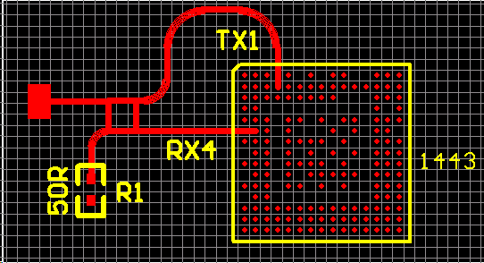
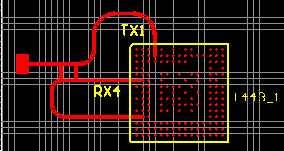
On the TI EVM IWr1443 you can see this on the EVM, the Rx antennas left to right are Shield, Rx1, Rx2, Rx3, Rx4, Shield, then the Tx antennas
Tx1, Tx2(elevated), Tx3.
You have two choices:
a) If you have a single patch for both Tx and Rx, you would use a Circulator Tx RF port -> Circ Tx -> Patch Antenna
Rx RF port <- Circ Rx <-
normally circulators are used when a waveguide is used for a horn antenna.
b) the preferred approach is to have a single Rx patch antenna, shield strip, and single Tx patch antenna. In this manner, the antenna port is directly connected to one Rx port.
Hello, Given the transport of P1 to an unused Rx ball, I would use a power divider, if this is 1/4, send the divided 1/4 to unused Rx.
Regards,
Joe Quintal