This thread has been locked.

If you have a related question, please click the "Ask a related question" button in the top right corner. The newly created question will be automatically linked to this question.

AWR1443BOOST: Configuration for Medium/Long Range Detection

Part Number: AWR1443BOOST
Other Parts Discussed in Thread: IWR1443

Hi, 

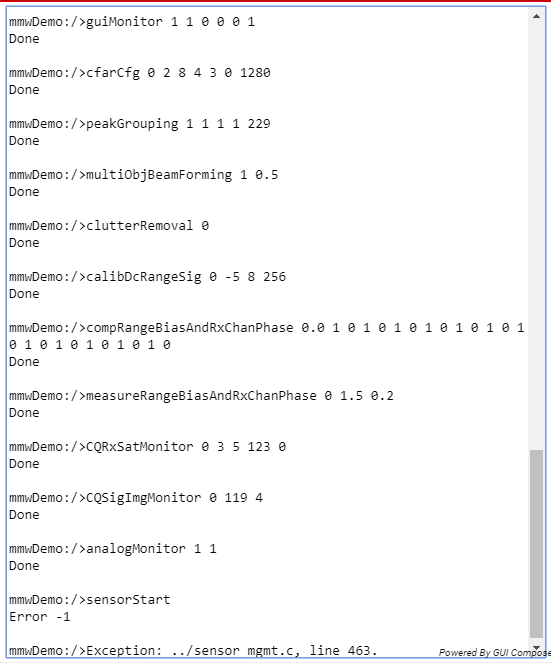
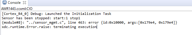
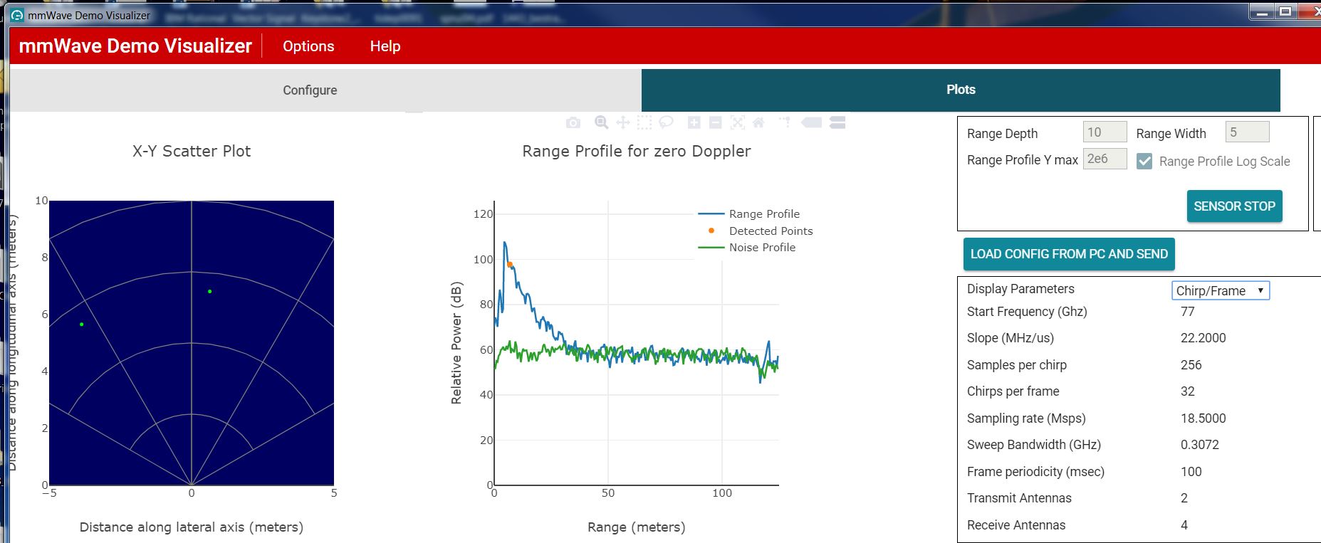
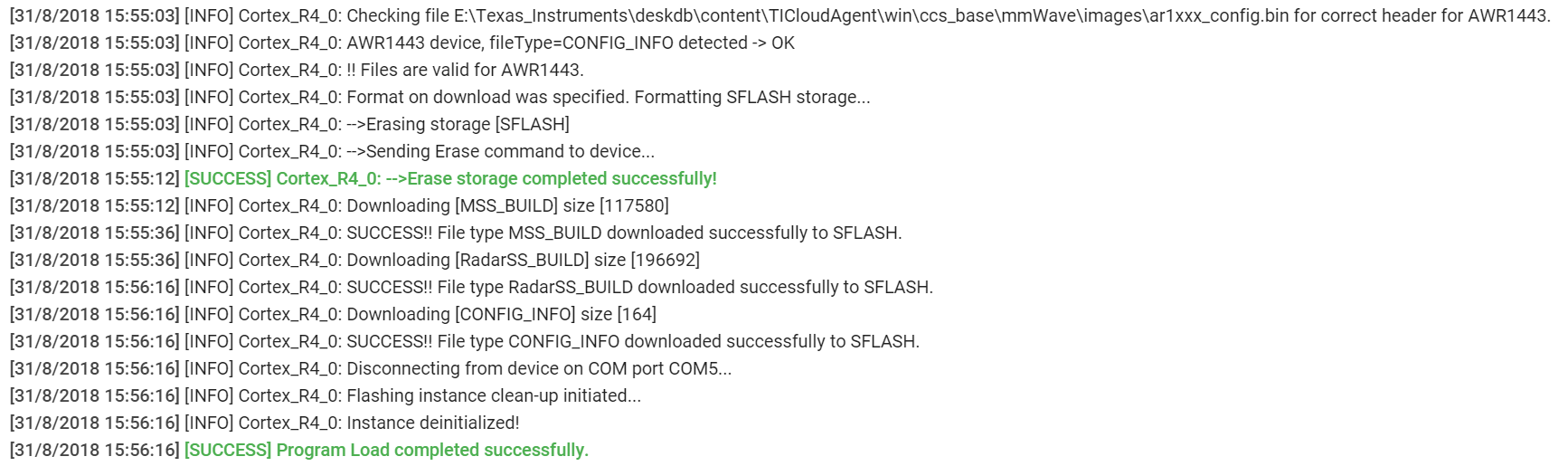
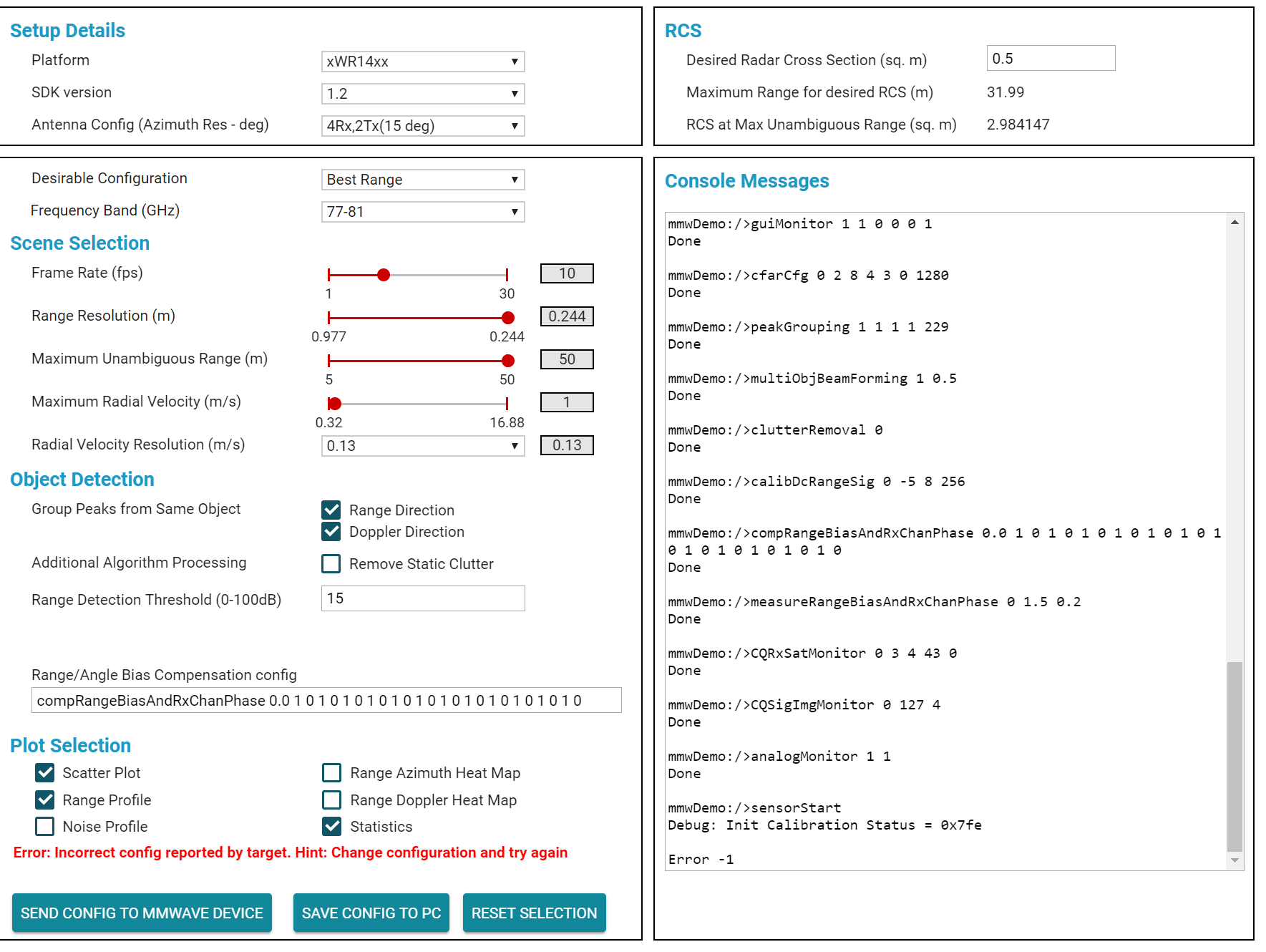
I have an AWR1443BOOST and I want to test it for different ranges and antennas' configuration. For this purpose, I'm using mmWave Demo Visualizer and mmWave SDK v1.2. When I use the GUI, I could achieve tests with antenna's configuration of 4Rx,2Tx and 4Rx,3Rx and Best Range Resolution (tests with 5m range), getting results on Plots windows. But when I try to get results for longer ranges, 15/20 meters, I have problems with configuration, even if I change to Best Range option or antenna's configuration (an example is in the images below). Could you give an advice to test long range detection? 

Regards,

Diego Justo

  • Hello,
    Some parameter that you have modified, is creating an error.

    Start with the IWr1443 configuration you loaded before modifications.
    (a) In your scene selection, max unambiguous range should be increased.

    (b) when you have maximized the max range, you can manually control the radar parameters, you will need to become familiar with these program parameters in srwa553, swra554a, and the Out of Box User Guide.

    If you want longer range examples, you would save your last working example to a .cfg file. Make sure you can load it from the Plots tab, and evaluate the results are OK. In the plots tab you would change the desired range, with the same .cfg file.

    If you create another .cfg file, and lower the Frequency Slope. You will proportionally increase the range. This is discussed in the mmwave_SDK User Guide under the docs folder, and swra553 . The Sensing Estimator is needed for system evaluation, eventually other parameters need to be considered, Detection SNR, RxLNA gain, and the antenna Field of View (this is in the IWR1443 BOOST User Guide.

    " www.radartutorial.eu/.../Frequency Modulated Continuous Wave Radar.en.html "

    In a research environment, if you wanted to convert to using C code, you could try the Out of Box demo, Capture section, this allows you to process the Radar Rx data. In advanced research, you would download mmwave studio (dfp), but you would need additional hardware TSW1400 + DevPack, or DCA1000. You do not need these additional tools for the Out of Box demos.

    Regards,
    Joe Quintal
  • Thanks a lot for the information,

    I'm going to review all documentation that you give me and test again the evaluation board. 

    Regards,

    Diego Justo

  • I read the documentation that you posted and I used mmWave estimator to select the correct parameter to include on the configuration file, but I still have configuration errors or error when the board start to work (I can't get any data in the Demo Visualizer). Could you give me some configuration file for the Demo Visualizer to test 30/50 m people's detection with the AWR1443BOOST?

    Thanks a lot for your help.
  • Hello,
    I will have to set this up in the lab. The key is to determine the FMCW parameters, modify the .cfg file, and then test it. It will be until Monday to have this done. You can look at swra553 Chirp setup. Take the shorter range example that works. Save t he .cfg file, edit and give it a new name. In the Profile Configuration command,

    In this example
    profileCfg 0 77 7 7 212.8 0 0 18.32 1 512 5000 0 0 40
    18.32Mhz/usec, will provide an IF frequency proportional to 2 * radial distance to the target.
    The DFE output rate is 5000ksps, so the max IF frequency is 4.5Mhz.

    In the frame configuration, as you increase the distance, you need to increase the mmwave sensor number of chirps.

    The minimum IF frequency design should be > 250khz.

    Using these two items, if the target is at 10meters, we expect the frequency to be 1.22e6.
    18.32Mhz
    5000ksps

    The max distance, 4.5Mhz IF, is 36.8m.
    If we reduce the Frequency Slope, this will decrease the expected frequency proportionally.

    Regards,
    Joe Quintal
  • profileCfg 0 77 1500 7 35.68 0 0 44.4 1 512 18500 0 0 30
    chirpCfg 0 0 0 0 0 0 0 1
    chirpCfg 1 1 0 0 0 0 0 4
    frameCfg 0 1 16 0 100 1 0

    Hello

    Here is an old example using the out of box demo.

    You can splice this into you current version.

    The setup should be for 1443, 4Rx, 2Tx MIMO (15deg azimuth resolution)

    Change the

    profileCfg

    chirpCfg(s)

    frameCfg

    I will try to test in the lab my Monday.

    Regards,

    Joe Quintal

  • Hello,

    I'm testing this new configuration and I'm going to test more possible configurations with your information.

    If you could share your results of Monday, I would appreciate.

    Thanks a lot for the information.

  • Hello,

    Could you try the configuration files in the laboratory? I tried the parameters that you posted, but Evaluation Board doesn't measure yet. 

    Thaks for your help. 

    Regards,

    Diego

  • Hello,

    I used mmwave SDK 1.2 , and an ES2 IWR1443 EVM, I configured the EVM for Out of Box demo, there are instructions in the mmwave SDK docs folder user guide.

    I aimed the mmwave sensor at the ceiling from my office desk.

    I have included the .cfg file (which you can load from the plots menu).  Sensor Stop, then Load from file.

    There is a .cfg, and a JPG of the Visualizer 2.0 used.

    To make the sensing example longer, I set the Frequency Slope to 1/2 the value, and increased the Rx LNA gain from 30->40db.

    There is also a picture of the Visualizer for this configuration, and a .cfg file.

    See if you get a similar response, the initial Best Range has a 50meter maximum, the modified is 100meters.  Note: the Sensing estimator provides the radar equation view of your mmwave sensor scene.  It is an estimation tool for configuration.

    Regards,

    Joe Quintal

    iwr1443_bestrange_sdk1p2.cfgiwr1443_bestrange_sdk1p2a.cfg

  • Hello,

    I tried to load the configuration file and I get an error in the console.

     I use the mmWave SDK v1.2 and I flash on the  AWR1443BOOS the file xwr14xx_mmw_demo_mss . In the board I only place the jumper SOP0. Could you give some advice to fix the problem?

  • Hello, In the Out of Box Visualizer, you need to select the proper device, the proper SDK version you have flashed.    Using the default OOB selection, with the device attached to the proper COM port, when you download to the device, capture the terminal window.   If there is an error, it can be either the configuration or the device.After you have flashed the device, reset the SOP2 jumper to removed.   Powered off/on the mmwave sensor.

    Then in the Visualizer, you have loaded IWR1443, SWver 1.2, Best Range.

    Note: If you do not see the appropriate terminal output, check the Serial port, reflash the EVM, with the appropriate mmwave SDK version.

    When you send the configuration you should see in the terminal window

    mmwDemo:/>sensorStop
    Done
    mmwDemo:/>flushCfg
    Done
    mmwDemo:/>dfeDataOutputMode 1
    Done
    mmwDemo:/>channelCfg 15 5 0
    Done
    mmwDemo:/>adcCfg 2 1
    Done
    mmwDemo:/>adcbufCfg 0 1 0 1
    Done
    mmwDemo:/>profileCfg 0 77 465 7 21.85 0 0 44.4 1 256 18500 0 0 30
    Done
    mmwDemo:/>chirpCfg 0 0 0 0 0 0 0 1
    Done
    mmwDemo:/>chirpCfg 1 1 0 0 0 0 0 4
    Done
    mmwDemo:/>frameCfg 0 1 16 0 100 1 0
    Done
    mmwDemo:/>lowPower 0 0
    Done
    mmwDemo:/>guiMonitor 1 1 0 0 0 1
    Done
    mmwDemo:/>cfarCfg 0 2 8 4 3 0 1110
    Done
    mmwDemo:/>peakGrouping 1 1 1 1 229
    Done
    mmwDemo:/>multiObjBeamForming 1 0.5
    Done
    mmwDemo:/>clutterRemoval 0
    Done
    mmwDemo:/>calibDcRangeSig 0 -5 8 256
    Done
    mmwDemo:/>compRangeBiasAndRxChanPhase 0.0 1 0 1 0 1 0 1 0 1 0 1 0 1 0 1 0 1 0 1 0 1 0 1 0
    Done
    mmwDemo:/>measureRangeBiasAndRxChanPhase 0 1.5 0.2
    Done
    mmwDemo:/>CQRxSatMonitor 0 3 4 43 0
    Done
    mmwDemo:/>CQSigImgMonitor 0 127 4
    Done
    mmwDemo:/>analogMonitor 1 1
    Done
    mmwDemo:/>sensorStart
    Debug: Init Calibration Status = 0x7fe
    Done
    When you see the following on the terminal screen.
    You then switch to the plots section.
  • Hello,

    I send you the version flashed in the Evaluation Board and the console messages (Uniflsh and mmWave Demo Visualizer).  I only have on the Evaluation Board the jumper SOP0 (SOP1 and SOP2 are removed). Could you give me some advice to solve the problem?

    Thanks for your help.

  • Diego,

    I can see that many chirp parameters you are passing are different from the default parameters used in the profile_2D.cfg file. I'd recommend using configuration instead.


    Cheers,
    Akash