This thread has been locked.

If you have a related question, please click the "Ask a related question" button in the top right corner. The newly created question will be automatically linked to this question.

DRV5055: Wire Break Detection

Part Number: DRV5055
Other Parts Discussed in Thread: DRV5057

Hello,

I would like you to confirm about below.

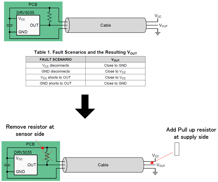
* According to datasheet, there is following figure and Table.

We understand that this connection (Vcc and OUT) can detect disconnect of Vcc and GND.

However, user can NOT detect disconnect of OUT in this case because OUT will become undefined state.

So customer will change connection of pull up resistor as shown below.

Customer understand that meaning of this pull ip resisor is only detection of disconnect.

Therefore, they can apply this change. However, if you have any concern about this change, could you please let us know ?

Best Regards,

  • Hello Machida-san,

    Thank you for using the TI forum. I tested the fail case for this scenario using a 5V supply and a 20KΩ pull-up resistor. With a disconnect on Vcc I saw 1.8V on Vout. This means that this new suggested setup case will not detect disconnect for Vcc.

    What I recommend is using the DRV5057, which should be available later this year. The DRV5057 is similar to the DRV5055, but has a PWM output. Because of this, you can better detect a failure mode by observing the existence of the PWM.
  • Hello Mitch-san,

    Thank you for your reply.

    I tested the fail case for this scenario using a 5V supply and a 20KΩ pull-up resistor. With a disconnect on Vcc I saw 1.8V on Vout. This means that this new suggested setup case will not detect disconnect for Vcc.

    1. I'm not sure why above difference will occur. The difference is just location of pull up resistor(supply side or sensor side). I think that same phenomenon will be observed in case of pull up resistor add on PCB(sensor side). Can you explain why this difference will occur ?

    2. My second question is this pull up resistor is just for detection of disconnect. Is my understanding correct ?

    What I recommend is using the DRV5057, which should be available later this year. The DRV5057 is similar to the DRV5055, but has a PWM output. Because of this, you can better detect a failure mode by observing the existence of the PWM.

    3. We have no chance to change device currently. So, We need to use analog output type device.

    BR,

  • Hello Mitch-san,

    I'm sorry I noticed that above two cases are different.

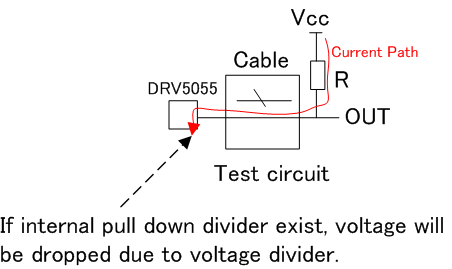
    In case of test circuit,

    When Vcc is disconnected, current path will be generated as shown above.

    If approx 10k ohm pull down resistor exist at "OUT" pin, voltage drop will be observed.

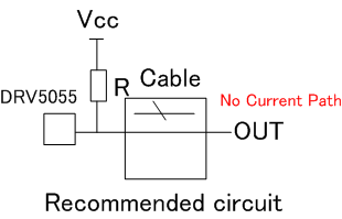
    On the other hand, in case of recommeded circuit,

    Even though Vcc is disconnected, no current path does NOT exist on "OUT" line.

    The difference b/w two is as shown above. Is my understanding correct ?

    BR,

  • Hello Machida-san

    To answer your questions above:

    1. Similar to your explanation above, when the resistor is on the device side of the cable and VCC is disconnected then no power can get to the device. However, when the resistor is on the source side of the cable and VCC is disconnected then there is still power on Vout through the resistor. This power actually slightly turns on the device, as well as drains through it, causing the output voltage to drop.

    2. Yes, this resistor is just for fault detection.