This thread has been locked.

If you have a related question, please click the "Ask a related question" button in the top right corner. The newly created question will be automatically linked to this question.

RTOS/AWR1642BOOST: HW Trigger Configuration Issue

Part Number: AWR1642BOOST

Tool/software: TI-RTOS

I am attempting to trigger the start of frames with the HW trigger (SYNC_IN) instead of the SW trigger (sensorStart) but I am having trouble. Here is my CLI configuration:

flushCfg
dfeDataOutputMode 1
channelCfg 15 3 0
adcCfg 2 1
adcbufCfg 0 0 1 1
profileCfg 0 77.001 429 7 57.14 0 0 70 1 256 5209 0 0 30
chirpCfg 0 0 0 0 0 0 0 1
chirpCfg 1 1 0 0 0 0 0 2
frameCfg 0 1 16 4 100 2 0
lowPower 0 1

Where the only real key difference between a HW and SW trigger configuration is the number "2" in the "frameCfg" command. When I run the above configuration with a software trigger, it successfully produces the following range-fft (ADC data extracted and plotted in MATLAB). 

Whenever I run the HW trigger configuration, I have no such luck with the output. Here is the range FFT that I plotted after extracting the ADC data after the HW trigger configuration script executed and I triggered a 5V square pulse on pin 9 on J6. The sensor did not even seem to turn on. I did not change the physical setup between the SW test and the HW test. 

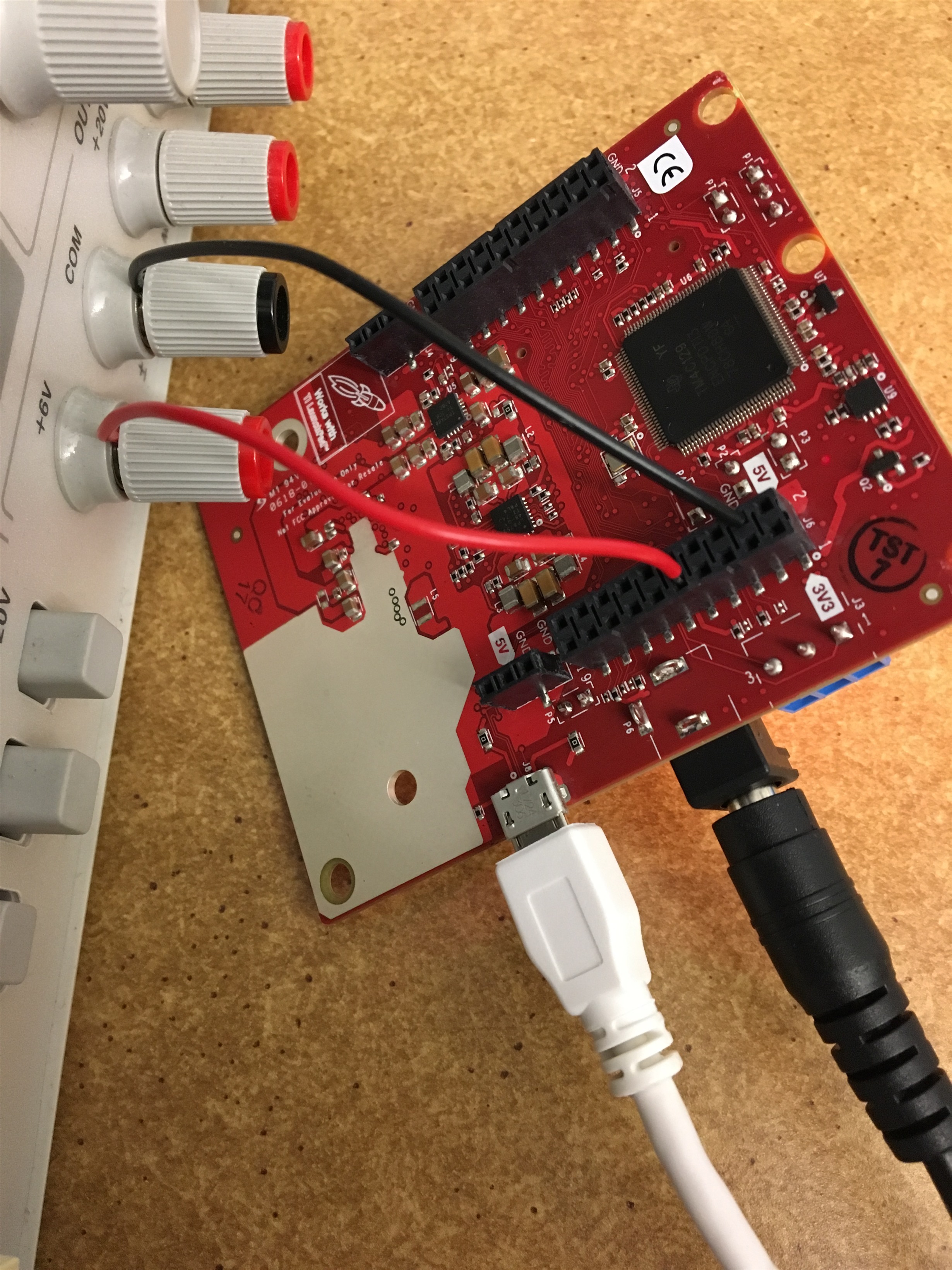
Here is the physical setup. For now, I just have it connected to a power supply that supplies 5V whenever I turn it on and 0V when I turn it off. I chose not to use a signal generator because I only wanted one pulse that I could easily control the timing of. After running the HW configuration script, I turn the power supply on, wait one second, and turn it off. I save the ADC data and plot it and nothing happens.

Do I need to have more than 1 pulse? i.e. does each 5V pulse trigger 1 frame? I don't understand what I am doing wrong. 

  • Hi,

    I don't think the mmwave SDK supports HW triggering. The mmwave SDK UG mentions for trigger select (sec 3.4 Configuration Format) that "only option for Software trigger is selected".

    Will confirm that and get back to you

    thank you
    Cesar
  • Thanks for following up. If you could clarify whether the "only option for Software trigger is selected" means that HW trigger will not work or that the HW trigger just was not tested, I would appreciate it. As a follow up question, I would just ask if the software-based trigger is the only means of starting a frame?
  • Hello Samuel,
    SW trigger means as soon as you invoke rlSensorStart API from the MSS/DSS application device will starting chirping.
    On the other hand in HW trigger mode you need to set frameConfig with '2' option and invoke the rlSensorStart API. Post this MSS/DSS won't get Chirp/frame interrupt as device is not yet started chirping. Device waits for HW trigger pulse over AR_SYNC_IN line.

    SYNC_IN pulse width must be less than the ACTIVE duration of single frame and more than ~9nsec.

    External SYNC_IN pulse periodicity should take care of the configured frame trigger delay and frame periodicity. The external pulse should be issued only after the sum total of frame trigger delay and frame periodicity.


    AR_SYNC_IN is not connected on EVM to J6-[9] pin, you to connect 0ohm resistor to R165. (refer EVMm schematic and assembly pdf). This is main reason it's not working with you setup and provided SYNC_IN pulse with the width mentioned above.


    Regards,
    Jitendra
  • Jitendra,

    Thank you for the response. I am marking this post as resolved, but will let you know if I have further questions!

    Sam
  •  Jitendra,

    Follow up question. It seems as though R165 is connected to the J6 - [9] pin?

  • So, in this case you need to provide pulse to this line SYNC_IN (3.3v) but SYNC_IN pulse width must be less than the ACTIVE duration of single frame and more than ~9nsec. As per above configuration ACTIVE duration is around 15 msec, so pulse duration (>9usec and <15msec).

    Regards,
    Jitendra
  •   Jitendra,

    I apologize for the continued problem, but I am still not getting results that I would expect. I resorted to the demo visualizer for the ease of viewing changes. Here is the configuration script I would load each time:

    sensorStop

    flushCfg

    dfeDataOutputMode 1

    channelCfg 15 3 0

    adcCfg 2 1

    adcbufCfg -1 0 0 1 0

    profileCfg 0 77 429 7 57.14 0 0 70 1 256 5209 0 0 30

    chirpCfg 0 0 0 0 0 0 0 1

    chirpCfg 1 1 0 0 0 0 0 2

    frameCfg 0 1 16 0 100 2 0

    lowPower 0 1

    guiMonitor -1 1 1 0 0 0 1

    cfarCfg -1 0 0 8 4 4 0 5120

    cfarCfg -1 1 0 4 2 3 0 5120

    peakGrouping -1 1 1 1 1 255

    multiObjBeamForming -1 1 0.5

    clutterRemoval -1 0

    calibDcRangeSig -1 0 -5 8 256

    extendedMaxVelocity -1 0

    bpmCfg -1 0 0 1

    lvdsStreamCfg -1 0 0 0

    nearFieldCfg -1 0 0 0

    compRangeBiasAndRxChanPhase 0.0 1 0 1 0 1 0 1 0 1 0 1 0 1 0 1 0

    measureRangeBiasAndRxChanPhase 0 1.5 0.2

    CQRxSatMonitor 0 3 5 123 0

    CQSigImgMonitor 0 127 4

    analogMonitor 1 1

    sensorStart

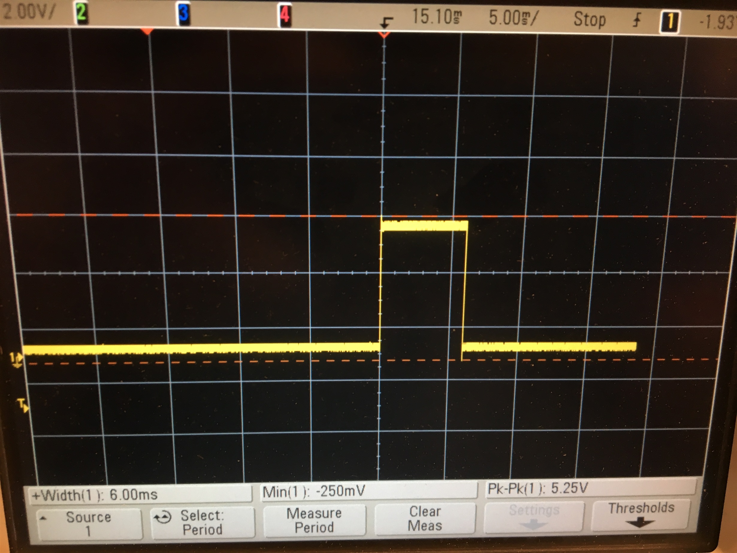
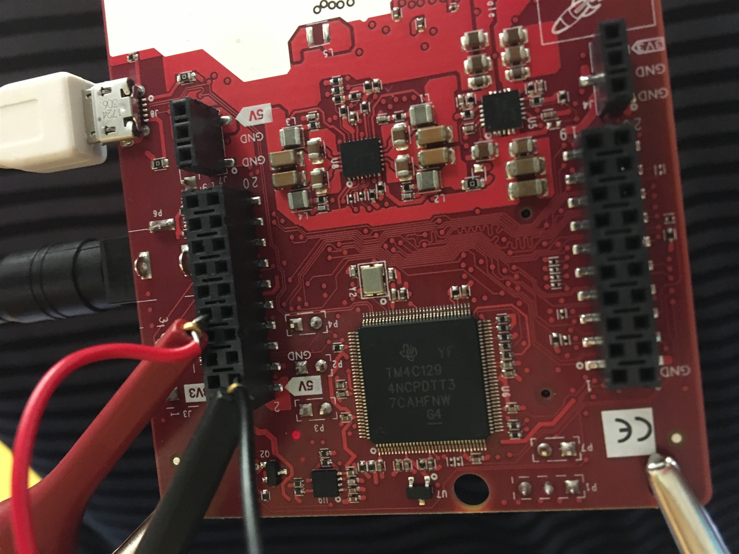
    After the sensorStart command, I provided a continuous waveform to the J6-[9] SYNC_IN pin that has an high period of 6ms (active frame is ~8ms) and has a low period of 94ms (100ms frame periodicity). Still, there was no observable changes in the mmWave demo visualizer. I am not sure what I am doing wrong.  Below is the verified waveform and pin connections.

  • Hi Samuel,
    Timing parameters and pulse width looks fine as per specification.

    Could you check in the DSS application for Frame/chirp interrupt counter after you provide first SYNC_IN pulse? Visualizer may or may not detect single frame output data.
    And on EVM by default R165 is not connected you need to connect it with 0ohm resistor. [re-writing it just for confirmation on HW].

    I see on different thread you can maked as answered is that mean this issue resolved at your end then we can close this same thread.
    e2e.ti.com/.../726449


    Regards,
    Jitendra