This thread has been locked.

If you have a related question, please click the "Ask a related question" button in the top right corner. The newly created question will be automatically linked to this question.

mmWave connecting to separate antenna

Other Parts Discussed in Thread: IWR1642

Hi,

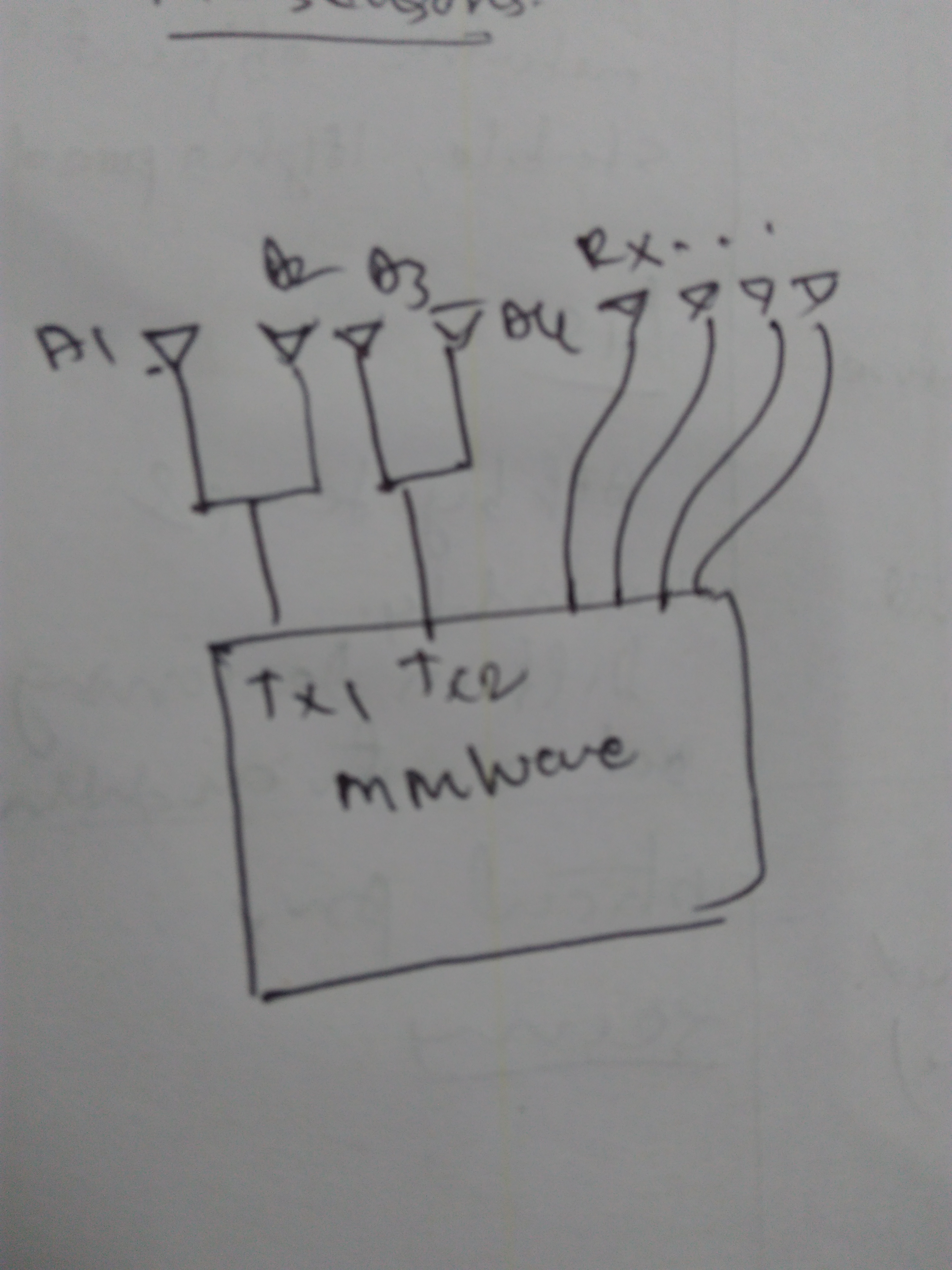
I want to use the mmWave IC for customized purpose where my FOV is more compared to existing patch antenna in AWR/IWR.so  I will design an antenna with custom spec and I want this antennas to be used to transmit and receive Chirp signals where waveguide will be connecting antenna PCB to mmWave PCB.

what precautions we have to take to do this modification in EVM board and How should we do that?

regards

'Karthik

  • Hello,

           There is no planned application note to  interface wave guide interface currently.  

    In the EVMs  for the RF traces after the package to board transition, the 50ohm GCPW transmission lines are routed to antenna ports.

    You may have to design a transition from 50ohm GCPW traces into WR12 waveguide interface to connect external horn Antennas. 

    There are many literature ( Just one example http://www.jpier.org/PIERL/pierl60/14.16040801.pdf ) and research papers you may want to explore more on this topic. 

    Thanks and regards,

    CHETHAN KUMAR Y.B. 

  • Hi Chethan,

    I got your point, but since you already have GPCW traces, what precautions I have to take for modification because I will have to remove the antenna PCB and connect it through transition to mmWave IC trace.

    regards

    Karthik

  • Hello Karthik,

    Sorry, reply button was pressed inadvertently before full message was typed.

    You need to consider following points :

    1) Matching Impedance should be close to 50ohm.
    2) Bandwidth of the transition should be large enough to pass the mmWave signal supported by our device, It's best if it supports 76-81GHz band to fully utilize the supported band by our device. If it's not possible then you need to choose that band and operate within that frequency band (Your range resolution would get limited, you may need to evaluate what value would be acceptable for your application)
    3) Goal is to keep your insertion loss at minimum, You may have to perform link budget analysis of your system for your application to budget what value of insertion loss that could be tolerated.
    4) Over all Return loss need to be kept better than -10dB across the desired band of operation.
    5) If you plan to use multiple transmitter and receivers then isolation need to be kept better than -20-25dB within Tx and Rx pairs.

    Thanks and regards,
    CHETHAN KUMAR Y.B.
  • Hi Chethan,

    For my application I would like to detect only, in range of 0 to 50 cm, in steps of cm.

    1. Yes, the impedance of transition should be 50.

    2.Since I want to have full sweep of 77-81 GHz, for 4 cm resolution,I will try to use the transition with same BW.

    3. The loss in transition, wave guide must be kept minimum

    4.across 77-81, loss should be less

    5.I did not understand this point.


    With IWR1642, I will try to use power divider to connect it to 4 Tx antennas.

    regards
    Karthik
  • Hello Karthik,

    For the 5. It's the isolation among the Transmitters and receivers, If you use more that 1 Transmitter and and 1 receivers, you need to ensure there is sufficient isolation between themselves so that it won't couple with each other.

    Thanks and regards,
    CHETHAN KUMAR Y.B.
  • Hi Cethan,

    Got your point.

    I want to use both Tx available on IC, but radiating antenna in 4 directions, So can I use power divider connecting to both transmitter so that I will get 2 output from each TX for antenna connection.

    Any specific requirement must be met or the loss already mentioned previously is only applicable?

    regards

    Karthik

  • Karthik,

    I'm not very clear with the end application you are targeting, even with single patch Antennas which radiates in 4 directions.
    If you need larger distance then Antennas have to redesigned specific gains in that direction.
    Could you please elaborate what you plan to do?

    Thanks and regards,
    CHETHAN KUMAR Y.B.
  • Hi Chethan,

    I will have separate  4 antennas in 4 different directions which has to be driven by single mmWave sensor.

    Yes, we will design separate antenna since we need wide FOV and will interface to mmWave through waveguide.

    In my application, I want to find out the range of target which can come in any one of 4 different directions. Since I need only range info I will use pair of TX and RX. since mmWave has 2 Tx, if I want to have 4 transmitting antennas I should use power divider at both Tx pins. The designed antenna will be interfaced to mmWave through waveguide.

    I have attached the image for reference.A1,A2,A3 and A4 are transmitting antennas in 4 different directions.

    Pls let me know for further explanation.

    Regards

    'Karthik s

  • What is the way to separate, the antenna PCB and mmWave EVM board, is since I want to connect new antenna designed through waveguide.
    Can we get the EVM chip without antenna PCB?
  • Karthik,

    You need to ensure, power dividers are designed appropriately, i.e. when you use power splitters there will be losses you need to budget in you Link budget calculations. Power splitters are also need to be matched at all the the ports i.e. Tx port and Antenna ports.
    Also higher isolation may be needed on the split out power ports. Very popular power splitter is Wilkinson power splitter, you may want to refer it for the power splitter designs.

    Thanks and regards,
    CHETHAN KUMAR Y.B.
  • Hi chethan,

    Got the point.

    One more question I had, what is difference between AWR 1642 boost, AWR 1642 ODS AND IWR1642 boost?
    Performance wise, wrt H/W ODS is having single patch antennas and wide FOV for short range
    AWR boost has array of patch antenna to have long range
    IWR has some more CAN connections what I got to know from other T2E conversations.

    Now the vital sign detection experimrnt or water level detecting is done using IWR. Can It be done also with AWR ? I mean same config files can be put to AWR from IWR experiments?
  • Karthik,

    Could you please raise a separate thread on newer questions, Essence is to capture newer questions with appropriate subject lines and reply's would be useful for other users who has similar question would be able to retrieve the answers easily by searching the threads in future.

    Thanks and regards,
    CHETHAN KUMAR Y.B.