This thread has been locked.

If you have a related question, please click the "Ask a related question" button in the top right corner. The newly created question will be automatically linked to this question.

RTOS/AWR1243: How to debug rlDevicePowerOn failure?

Part Number: AWR1243
Other Parts Discussed in Thread: TDA2PXEVM,

Tool/software: TI-RTOS

Hi, 

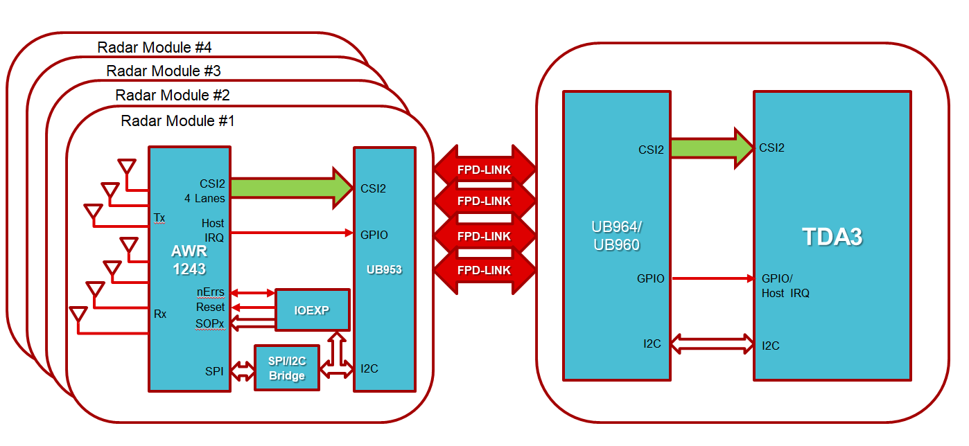
I am developing on the TDA2PXEVM + fusion board with a custom AWR1243 board and D3 IMX390. 

When I run the camera + radar combo usecase from the vision SDK, rlDevicePowerOn fails because it never receives the asynchronous event AWR_AE_DEV_MSSPOWERUPDONE_SB.

Attached is the sequence of bytes sent to the radar chip over I2C: 

I2C Bytes.xlsx

How can I verify the meaning of these bytes and/or whether these are the correct initialization bytes? The radar interface control document mentions that the "mmWaveLink Framework internally does some handshake with each connected radar device," but doesn't describe said handshake in more detail? 

When I probe the I2C, I can see ACKs coming back from the I2C to SPI bridge. However, when I probe the SPI, no response comes back from the AWR1243, either over the MISO, HOST_INTR, or ERROR_OUT.  

I have verified that the data makes it over the I2C to SPI bridge correctly, and that the radar chip is powered, not held in reset, and is clocked. 

Any help with debugging this issue would be greatly appreciated. 

Thanks,

Richard 

  • HI,

    Looping in the TDA team

    Thank you
    Cesar
  • Hi Richard,

    On the D3 AWR1243 module, it has an IO expander connecting to AWR1243 SOPx pins.
    We first configure the IO expander via I2C to set the SOPx pins to SOP Mode 4 before bringing AWR1243 out of reset.
    Is this being done on your custom Radar board?

    After that, if AWR1243 boots properly, you should see AWR1243 drive the HOST IRQ line HIGH.

    Please make sure you have observed the above sequence on your custom radar board.

    Regards,
    Stanley
  • Hi Stanley,

    About 16 milliseconds after bringing the AWR1243 out of reset, I see the HOST IRQ driven high. However, the serial terminal still outputs "Radar Device Power On failed." What else needs to be satisfied for the asynchronous event to happen?

    Thanks,
    Richard
  • Hi Stanley,

    When I look at the UB953 serializer register values for the AWR1243:

    BspUtils_Ub960I2cParams gUB953SerCfg[] = {

    {0x01, 0x01, 1000},

    {0x0E, 0x04, 10},

    {0x0D, 0x00, 10},

    {0x33, 0x07, 10},

    };

    The setting for register 0x0E indicates that only GPIO2 is enabled, and as an input. So how does the software bring the AWR1243 into and out of reset? Is that accomplished via the I2C? If so, does that correspond to any of these I2C bytes transmitted:

    2063.I2C Bytes.xlsx

    Thanks,

    Richard 

  • It is done via I2C command to an IO Expander.
    Please refer to BspUtils_resetAR12xxToSOP4() in ~/pdk_xx_xx_xx_xx/packages/ti/drv/vps/examples/utility/src/bsputils_ub960.c.
    This controls the reset line and SOPx lines.
    How is this done on your custom radar board?
  • Hi Stanley, 

    Our board does not have an IO expander, the AWR1243 is connected to an I2C-to-SPI bridge, which is connected to the serializer. Would it be possible to replace the IO expander addresses with the GPIO addresses on of the I2C-to-SPI bridge and perform the reset that way? 

    Thanks,

    Richard  

  • Hi Richard,

    I2C-to-SPI bridge path is for radar configuration only.
    Reset/SOPx lines are control signals on AWR1243. They should be tied to some GPIO lines on the Host side (TDA2P) if Radar is directly connected to the Host.
    For FPD-Link connection type, due to the limited number of GPIOs available on UB953/UB960, we have to add IO Expander to have enough number of IO pins to connect Reset/SOPx lines on AWR1243 and then control those lines via I2C to UB960/UB953.

    Regards,
    Stanley
  • Hi Richard,

    Please refer to the below block diagram for the connection details.

    Regards,
    Stanley


  • Hi Stanley,

    I can't find the SOPx pins in the AWR1243 datasheet, do they have an alternate name and/or what are their pin numbers?

    Thanks for the quick response,
    Richard
  • Hi Richard,

    I think it is a typo in the datasheet. In Page 33 of datasheet, which is the schematics, you will find xx_xx_SORx pins. Those are the Sense-on-Power pins a.k.a SOP pins.

    SOP0 = TDO
    SOP1 = SYNC_OUT
    SOP2 = PMIC_CLKOUT

    You can refer to bootloader flow doc below for how bootloader reads the status of the pins.
    www.ti.com/.../swra561.pdf

    They should be SOP[2:0] = 001 at the boot time so bootloader will start AWR1243 in functional mode.

    Regards,
    Stanley
  • Hi Stanley, 

    We currently don't have the the SOP pins brought out. Will the AWR1243 default to functional mode if the SOP pins are floating? 

    In addition, we are looking into adding the IO expander to our design, can you provide us with the part number? 

    Thanks,

    Richard 

  • Richard,

    You would need to bring the SOP out. This is what the AWR ROM senses before going into Functional and other modes.

    Thanks and Regards,
    Piyali