This thread has been locked.

If you have a related question, please click the "Ask a related question" button in the top right corner. The newly created question will be automatically linked to this question.

IWR1443: How execute the downloaded secondary bootloader?

Part Number: IWR1443

Hi:

I have a client who wants to have a software update through CAN.

I have programmed a primary bootloader, that will check the if it is able to boot into the application. If it cannot it will wait for the PC to send a secondary bootloader which contains the QSPI flash to update the application software in the QSPI.

My question is, in the device, where I can temporarily store this SBL and execute it?

It seems like I cannot use memcpy to the addresses in TCM RAM-A. It might be write-protected, is it?

However, I can write into the TCM RAM-B but when the PBL execute the SBL using the addressed entry point(_c_int00), the core crashes and said the address is (no symbols are defined). BTW, I have confirmed this address is the same address in the SBL map file. 

Thank you.

  • Hello,

    The TCMA memory may be setup as read-only via the MPU settings in the ARM processor. Please see the "MPU (Cortex R4F)" information in section "5. 4. 10. 2. SOC" in the mmWave SDK 1.2 user guide for more information. Please especially note the "DOWNLOAD_FROM_CCS" build-time option which can be used to enable write-access to TCMA.

    The TCMB memory is configured as non-executable by the mmWave SDK by default. Please see the _mpuSetRegion API calls immediately after the following comments in C:\ti\mmwave_sdk_01_02_00_05\packages\ti\drivers\soc\platform\soc_xwr14xx.c.

    /*
    Setup region 3, TCMB DRAM, base address = MSS_TCMB_BASE_ADDRESS, size = 64KB,
    Access Permissions: Full Access
    Execute Permissions: Execute Never
    Memory Type: Non-Cached, Non-Shared, Normal
    */

    The _mpuSetRegion API calls are described in the mmWave SDK Doxygen documentation by clicking on SOC->Files->soc_mpu.h after opening the following file.
    C:\ti\mmwave_sdk_01_02_00_05\docs\mmwave_sdk_module_documentation.html

    The direct link is:
    file:///C:/ti/mmwave_sdk_01_02_00_05/packages/ti/drivers/soc/docs/doxygen/html/soc__mpu_8h.html

    You can also look at the following link for more information on the details of the ARM Cortex R4F MPUs.
    infocenter.arm.com/.../Biijbjie.html

    Please mark the thread as answered if your question is resolved or reply if more support is needed.

    Regards,
    John
  • Hi John:
    Thanks for your explanation.
    Now I understand I may need to download the SBL in the TCMA instead of the TCMB.
    I still not clear on how to execute the SBL using the ENTRY POINT(_c_int00). Can I just call that address to start the main function?
  • Hi John:
    How to find out the address in TCMA that I am able to memcpy the SBL program into?
    I think the PBL needs to use some of the space in the TCMA, so the SBL program cannot use the addresses that PBL is using, but how to find out the free spaces(addresses) that the SBL program can be used?
  • Hi John:
    If I understand correct, by set DOWNLOAD_FROM_CCS to yes, I should be able to write(memcpy) into the TCMA, is that right?
  • Hi John:
    I am able to use the CAN to download the SBL into TCMA. Thanks for your help.
    Now, I want to execute the SBL from the PBL through the entry_point in the SBL. I got the exception "no symbols are defined" on the address of that entry_point. Then I tracked into the ASM, I found there is no symbol in that address.

    So the question is what should I do before I tell the PBL to execute the SBL by loading the entry point?

    Thank you.
  • Hi,

    Here is some information from another thread regarding the "no symbols are defined" message you are seeing in CCS:
    "No symbols defined in CCS just means that the CCS IDE is unable to correlate the assembly code in a particular memory section with any symbols or code from the search path. IF the core is being loaded by some other core or host then you will need to go to Run->Load Program-> Add Symbols and load that out file to see the symbols located at that location in memory."

    As additional information, one way to make sure the processor is in a clean state when starting the new application is to first write all the new application code to RAM (except the new interrupt vector table) and then write the interrupt vector table from the new application to the start address of the ARM (address 0x0) and then perform a soft reset of the ARM core. The soft reset can be performed as described in section "3.7.2.1 SOFTRST1 Register" of the IWR1443 TRM (i.e. by writing "0xAD" to the SOFTRST1 Register at address 0xFFFFFF04).

    Regards,
    John
  • Hi JohnH:

    Thanks for your reply.

    Is the interrupt vector table has to be started at address 0x0? I am wondering if I can have different vector tables for the PBL and the SBL. 

    I put the Linker file of my SBL below, please take a look:

    /* Linker Settings                                                            */
    --retain="*(.intvecs)"
    --entry_point="_c_int00"
    /*----------------------------------------------------------------------------*/
    /* Memory Map                                                                 */
    MEMORY{
        /* Flash */
        m_dst1         (RX)  : origin=0x00009000 length=0x00001000
    
        VECTORS        (X) :  origin=0x0000A000 length=0x00000100
        PROG_RAM       (RX) : origin=0x0000A100 length=0x00007B00
    
        DATA_RAM       (RW)  : origin=0x08007C00 length=0x000083FC
        m_resetreason  (RW)  : origin=0x0800FFFC length=0x00000004
    }
    
    /*----------------------------------------------------------------------------*/
    /* Section Configuration                                                      */
    SECTIONS{
        .intvecs : {} > VECTORS
    
        .text    : palign(2) {} > PROG_RAM /*7.5.4.2.5 CCS Helper*/
        .const   : palign(2) {} > PROG_RAM
        .cinit   : {} > PROG_RAM ALIGN(16)
    
        .bss     : {} > DATA_RAM
        .data    : {} > DATA_RAM
        .stack   : {} > DATA_RAM
    
        .dst1 :
        {
          . = ALIGN(4);
        } > m_dst1
    
        .mcu.resetreason (NOLOAD) :
        {
          . = ALIGN(4);
        } > m_resetreason
    }
    /*----------------------------------------------------------------------------*/

    The m_dst1 is the section for some info about the part no, shared with the PBL. 

    The VECTORS and the PROG_RAM are the places for the SBL. 

    If I understand correctly, the VECTORS should be from 0x0, however, the VECTORS of the PBL is also started from 0x0. 

    Can I copy the VECTORS of the SBL from 0x0, should I worry about the data from PBL been covered?

    Thanks for your support. 

  • Hi JohnH:
    I have an additional question.
    How the CCS load and execute the program in RAM?

    In the CCS, I can see all the SBL program data has been successfully downloaded into the RAM and the new interrupt vector table copied to the address 0x0. But after the soft reset, the new application(SBL) locates in the new address is not loaded.

  • Hi:

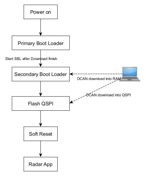
    I think I need to explain a little bit more about what I plan to do.

    1. There will be a primary bootloader runs as an application. This primary bootloader will be located in the Flash and executed after the power turns to on.

    2. This primary bootloader(PBL) tries to execute the Radar Application. If it cannot it will stay in the primary bootloader mode and wait for the Secondary bootloader(SBL) to be downloaded through CAN. The SBL is programmed into the SREC file by the armhex tool.

    3. The SBL will be located in the TCMA. The PBL will execute the SBL after it has been successfully downloaded. 

    4. The SBL includes the function to reflash the QSPI. The data of the Radar Application will be downloaded into the QSPI. 

    5. Reset the MCU and back to 1. 

    Here is the flow chart:

    The problem I am currently experiencing is, the SBL is completely downloaded, and it locates at the address that I wanted. However, the PBL cannot execute the SBL by the entry point of the SBL. For example, the entry point is in the address 0x0001bb1c, if the PBL call the address, it will crash. The Hex data in the address is the same in the SREC file. 

    So I think it is not just called the entry point, there must something else has to be done before it. 

    But I have no clue how to find the solution. 

    I hope you understand what I just said. 

    Thanks for your support.

  • Hi:
    I am very looking forward to seeing the solutions.

    Best Ragars
  • Hello,

    Normally the entry point of a program assumes that the processor and system are in a certain state (i.e. privelege level, MPU setup, etc.). Therefore executing an entry point of another program directly from the first program could cause issues. Would it be possible to try the solution I mentioned for executing the SBL? For example, write the interrupt vectors for the SBL to address 0x0 and perform a soft reset to see if it resolves the issue?

    Thanks,
    John
  • Hi:
    I have tried that solution.
    Maybe I am not doing it right.
    The PBL downloaded the SBL with the interrupt vector first. Then copied the interrupt vector to address 0x0 before the soft reset.
    But the program stopped at the 0x00000010, and the point of the _c_int00 remains at the PBL instead of change to the SBL.
    Is there any configurations need to be done before the soft reset?
  • Hello,

    Could you clarify what you mean by "the point of the _c_int00 remains at the PBL instead of change to the SBL"? Are you referring to which address CCS associates with the "_c_int00" symbol? If so, then that mapping is just controlled by which symbols you have loaded into CCS. If you have only loaded the first application (which includes its own symbols) using CCS then CCS will only know about the symbols from the first application. You would need to load symbols from the new application (preferably after the new application has been started) to tell CCS about the new symbol to address mapping.

    If the processor is at location 0x10 then that may be a Data Abort. Please see the Cortex R4F information in the following app note which gives some details about exception handling.
    www.ti.com/.../spna218.pdf

    Please also confirm that the new application performs all the system initialization as described in section "5. 4. 10. mmWave SDK - System Initialization" in the mmWave SDK 1.2 user guide.

    Regards,
    John
  • Hi:
    Sorry about my unclear description.
    I mean the pointer address in the disassembly of the _c_int00. I only load the PBL program in the CCS, and the SBL is the one that downloaded by the PBL program into the RAM.

    The system initialization has been done in the PBL, such as ESM, SOC and PINMUX. Since the SBL is not executed appropriately, the main function is not running. 

    I am wondering, is it possible to run the application by another running application while they have the different entry points?


    Regards
    Jianyuan

  • Hello,

    I think there may be some confusion about _c_int00. _c_int00 is simply the name of the symbol of the C environment entry point for a compiled program. You can see the address of the _c_int00 symbol for a specific compiled MSS program by looking in the .map file in the build directory. For example, I see the following in my current 14xx mmw demo .map file (C:\ti\mmwave_sdk_01_02_00_05\packages\ti\demo\xwr14xx\mmw\xwr14xx_mmw_demo_mss.map).

    OUTPUT FILE NAME: <xwr14xx_mmw_demo_mss.xer4f>
    ENTRY POINT SYMBOL: "_c_int00" address: 00015568

    When you load a program into the mmWave device using CCS, CCS uses the symbol-to-address mapping information in the compiled binary to associate the _c_int00 symbol with the desired address for that program. This helps when debugging because CCS can take you to the associated address when you tell it to go to the _c_int00 symbol, but does not affect the code running on the device. CCS will also show this symbol in the disassembly view for that address.

    If the device starts running code that was not loaded by CCS, then CCS will not automatically know about the new symbol-to-address mapping for the new program. In order to tell CCS about the new mapping, you can go to "Run->Load->Load Symbols..." and give it the new application binary (<new_application>.xer4f file). Then CCS will use the symbols from that new program and will show _c_int00 mapped to the entry point of the new program. Again, this just changes what CCS shows for debugging purposes but does not change the actual program operation on the device at all. You can try this after the new program starts running to see the _c_int00 symbol mapped to the new program entry point.

    Regards,
    John
  • Hi John:
    The solution you promoted was working.
    I found the memcpy copied the data in little-endian format, so the data in address 0x0 is swapped. After I swapped them again before soft reset, the SBL starts to run.
    Sorry for the trouble, the problem is solved. I will mark this reply as resolved.

    Thanks
    Jianyuan Ma