This thread has been locked.

If you have a related question, please click the "Ask a related question" button in the top right corner. The newly created question will be automatically linked to this question.

FDC2214

Other Parts Discussed in Thread: FDC2214, FDC1004, FDC2214EVM

HI 

I'm Working on FDC2214 EVM for liquid level sensing.

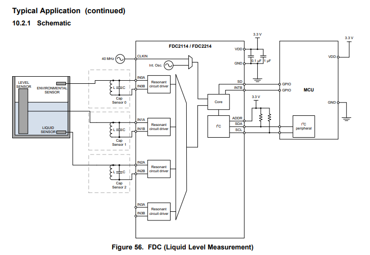
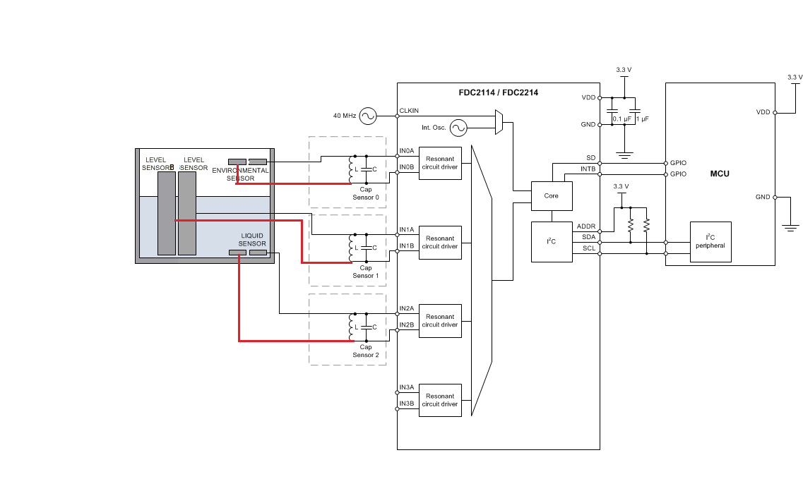
I've connected level electrode to INOA and reference electrode to IN1A.

I've shield electrodes (one for level electrode and another for reference electrode (SHLD1)).

Next, I've Shield electrode (SHLD2 ) connected to ground electrodes.

Now, where should I connect these shield electrodes on  FDC2214 EVM?

Can I get connections of level electrode, reference electrode and its corresponding ground electrodes to be connected to FDC2214 EVM?

Waiting for your response.

Thank you and Regards,

Vignesh

  • Hi Vignesh,

    The FDC2214 can use either an active or a passive shield. For an active shield, connect a buffered signal of the INxA pin to the Shield electrode. You will need an external amplifier to do this. For a passive shield, connect ground instead. See section 10.1.2 of the datasheet for more details.

    Where are you using ground electrodes? The figure below (from the datasheet) is the typical schematic for liquid-level sensing applications using the FDC2214.

    Regards,

  •  Hi Kristin,

    Thank you for your reply.

    I think the above schematic is for Single ended measurement. Am I correct?

    So if I need to have differential measurement, I need to include the another electrode adjacent to level electrode,  reference electrode and environmental electrode like I've attached the schematic above.

    Also, I've shield electrodes (SHLD1 and SHLD2 as in FDC1004) on other side of my Capacitive sensor design. Where I need to connect these shield electrodes or it's not needed for FDC2214?

    Further, what is the use of LC tank circuit on FDC2214 EVM? Can you explain it briefly?

    Next, whether the ground shifting technique should be followed for proximity sensing or Liquid level measurement?

    Finally, Is there any breakout board for FDC2214?

    Waiting for your kind response.

    Thank you and Regards,

    Vignesh

  • Hi Vignesh,

    You are correct that the schematic I shared is for single-ended measurement. You've also correctly modified the schematic to use differential measurement.

    The LC tank is critical to the function of the FDC2x1y devices. These devices drive an LC tank (the sensor) at its resonant frequency. When shifts in capacitance cause the frequency of the LC tank to change, the device can measure this. The output of the FDC2x1y devices is a digitized ratio of the sensor frequency to a reference frequency. For more information about the resonance-based architecture for capacitive sensing and how it differs from traditional capacitive sensors, please see this blog post.

    Because the LC tank is inherently a narrow band-pass filter, the FDC2x1y devices are immune to broadband noise, unlike traditional capacitive sensors like the FDC1004. While it is critical to use the shield for FDC1004 applications, it is not nearly as important for FDC2x1y devices. The main reason to use a shield for FDC2x1y applications is to prevent certain areas from being included in the sensor. This could include long traces or cables, or it could include the back of the sensor plate.

    If your application will not be connected to Earth ground, or the FDC2x1y section of the device will be separated from a much larger ground plane by a cable, I would follow the system ground design outlined in the ground shifting application note.

    Finally, we do not have a breakout board for the FDC2214, only the FDC2214EVM. However most key signals from the FDC2214 are broken out on the FDC2214EVM, so it should be usable for most testing purposes.

    Regards,