This thread has been locked.

If you have a related question, please click the "Ask a related question" button in the top right corner. The newly created question will be automatically linked to this question.

PGA450Q1EVM: Few questions about PGA450q1 behavior

Part Number: PGA450Q1EVM
Other Parts Discussed in Thread: PGA450-Q1, , TIDA-00151

Hi,

In order to better understand the behavior of PGA450q1, I have few questions:

1. We want to build a programming and debugging tool for PGA450q1. In order to communicate with a pristine PGA450q1 using SPI, the PGA450q1 must be in a reset state. What will be the process putting the PGA450q1 in a reset state?

(We are using this socket -> https://www.mouser.com/ProductDetail/adafruit/1280/?qs=GURawfaeGuBaGCXLK7N1zQ%3d%3d&countrycode=US&currencycode=USD

connected to a TIGER board via SPI (SDI, SDO, CS and SCLK), and applying a 12v to vpwr)

2. According to PGA450q1 EVM user manual the soldered PGA450q1 is loaded with dev ram. The dev ram supposed to be wiped every power cycle, but we can see that after power on we can still measure distance or any other functionality of the EVM. Can you please clarify that?

3. On PGA450q1 EVM - is it possible to read the eeprom and other registers of a pristine PGA450q1 which is placed into the socket (not the soldered one)? or the only available functionality is programming the OTP / DEV ram?

Thanks,

Eyal

  • Hi Eyal,

    1. Refer to section "7.4.3 RESET" of the PGA450-Q1 datasheet for the procedure on placing the internal 8051 in and out of reset:

    7.4.3 RESET
    The PGA450-Q1 can also be put into a RESET state where the microcontroller is not active. During this state,
    SPI is the only digital interface that can be used. The low-side drivers can still be triggered to begin an ultrasonic
    burst and the analog front-end and digital data path can still store the returned echo signal in the FIFO RAM.
    However, any processing of the FIFO RAM by the internal microprocessor to determine the location of an object
    does not occur. The FIFO RAM data can be read over SPI, allowing an external microprocessor to process the
    data.
    While the microcontroller is active, the MICRO RESET test register is the only register accessible through SPI.
    The device must be put into the RESET state before sending additional SPI commands.
    The maximum current (VREG not charging) in the RESET state is 15 mA.
    To put the microcontroller in reset, write a 1 to bit 0 of the MICRO RESET (address 0x2F) test register. Transmit
    the TEST Write SPI command in the following order: 0x16, 0x2F, 0x01.
    To bring the microcontroller out of reset, write a 0 to bit 0 of the MICRO RESET (address 0x2F) test register.
    Transmit the TEST Write SPI command in the following order: 0x16, 0x2F, 0x00.
    NOTE
    The MICRO RESET (0x2F) register is an internal test register, which is why the field is not
    listed in the SFR or ESFR register map.

    2. The PGA450Q1EVM should be "Programmed to Jump to DEVRAM". To confirm if the PGA450-Q1 installed on the PGA450Q1EVM has been OTP programmed to run from OTP or DEVRAM, refer to section "9.5.3 Verify OTP Programming" of the PGA450Q1EVM User's Guide:

    Check OTP Status

    Ensure the MICRO is in the RESET state. Press the "Check OTP Status" button to verify what is currently programmed into OTP. The three possible results are:

      • Programmed to Jump to DEVRAM: The jump to DEVRAM statement has been programmed into the OTP. This means that programs loaded into the DEVRAM will execute.
      • OTP Empty: Nothing has been programmed in the OTP.
      • Programmed: The OTP has been programmed with something other than the jump to DEVRAM statement.

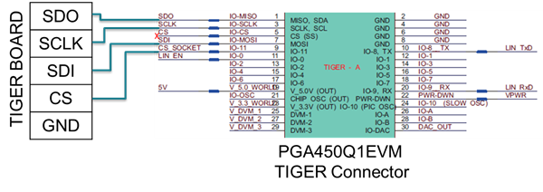
    3. Yes, it is possible to read, write, and program all registers of a device placed on the EVM socket (U3). To best method of ensuring you will only communicate with the socketed device is to detach the TIGER board from the PGA450Q1EVM, and jump wire the SPI pins from the TIGER to the PGA450Q1EVM with one change. The TIGER's CS pin will connect to the PGA450Q1EVM TIGER connector's CS_SOCKET pin. This will ensure only the socketed device processes the GUI commands, while the soldered device will be inactive. Be sure to ground the TIGER to the PGA450Q1EVM board.


  • Thanks a lot!

    Regarding #3:
    Is it possible to communicate with the PGA450q1 which is in the socket over UART?

    Thanks,
    Eyal
  • Hi Eyal,
    The UART pins from the socketed device are not routed to any headers on the PGA450Q1EVM, only the SPI, so you would need to jump wire the UART pins from the socket connector's vias to your UART master.
    If you intend on using the TIGER board to check UART, communication, use the TIGER's UART pinout and instruction shown in the "PGA450Q1EVM-S User's Guide and TIDA-00151 UART Demo Instructional" ( www.ti.com/.../sldu019 ).