Other Parts Discussed in Thread: TIDEP-0091
Hello,
We have a designed a PCB for a custom form factor / application that utilizes the IWR1443 radar chip. Currently we are not able to pass the sensorStartup calibration. We have ran the OOB demo with updated mmWaveSDK and have full UART and JTAG communication.
1) Can someone explain or point me to the radarSS calibration procedure? (not the range offset procedure)
2) Can someone explain how to change the bit-mask for calibration to force the sensor to pass or bypass calibration?
3) Is their a convenient location to do this without recompiling the radarSS.bin file via RadarStudio?
4) Is there a way to bypass calibration and force chirping to begin? We hope that it might lead to another clue as what is wrong in our design?
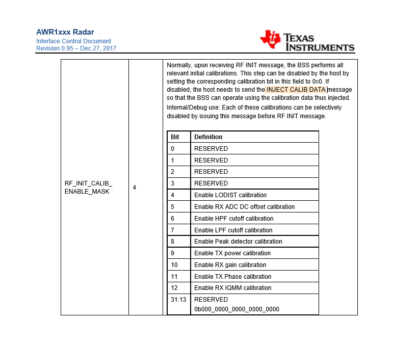
Below is the bitMap of the calibration configuration. We usually see callibration Status = 0x1fe or 0x3fe returned after calling "sensorStart" from the CLI. Does this bit map relate directly to the calibration status I get back after calling sensorStart? Where does the value returned, fit within this bit Map?
If we are returned 0x1fe = 000111111110, does this indicate that I am failing tests as shown below?
Bit 0 = 0 - Reserved
Bit 1 = 1 - Reserved
Bit 2 = 1 - Reserved
Bit 3 = 1 - Reserved
Bit 4 = 1 - Passed LODIST Callibration
Bit 5 = 1 - Passed RX ADC DC offset calibration
Bit 6 = 1 - Passed HPF cutoff calibration
Bit 7 = 1 - Passed LPF cutoff calibration
Bit 8 = 1 - Passed Peak detector calibration
Bit 9 = 0 - Failed TX power calibration
Bit 10 = 0 - Failed RX gain calibration
Bit 11 = 0 - Failed TX Phase calibration
Bit 12 = 0 - Failed RX IQMM calibration
Thanks.