This thread has been locked.

If you have a related question, please click the "Ask a related question" button in the top right corner. The newly created question will be automatically linked to this question.

CCS/IWR1642: CCS

Part Number: IWR1642
Other Parts Discussed in Thread: MMWAVE-SDK, , IWR1443,

Tool/software: Code Composer Studio

Hi,

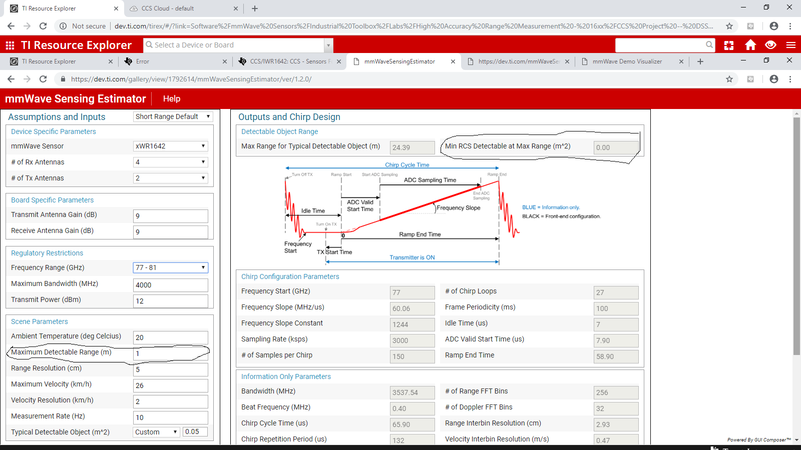
My application is like: I want to detect an object which is at a distance of few cm from the mmWave radar. I want to compare the range of this detected object and if it is less than some threshold (I will decide the threshold), one GPOI pin should be made high.

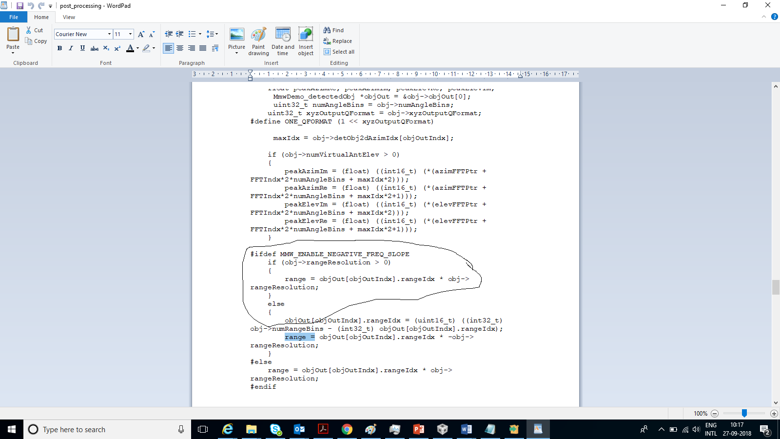
Please help me with any demo where do I need to modify to get this done.

Went through some lab examples, but not able to understand complete code.

Regrads

Karthik S

  • Hi Karthik,

    The mmWave SDK mmw demo can be used to produce a point cloud of detected objects. It is described in the MMWAVE-SDK user guide. When detecting a single object it's accuracy is around 1cm. You can build the source code using makefiles by following the instructions in the mmWave SDK user guide. Alternatively, you can build using CCS by following the instructions for the corresponding lab in the TI Resource Explorer at the following link (IWR16xx version).
    dev.ti.com/.../

    If more accuracy is required you may want to try out the High Accuracy lab on the TI Resource Explorer. The IWR1642 version is at the following link where you can find the setup guide with more information.
    dev.ti.com/.../

    Regards,
    John
  • Hi,

    Could you pls elaborate

    1. How can I find the range vaule

    2. Where do I compare the this range value with threshold and make GPIO pin high

    requesting to show in code since I am not good at coding, kindly help to identify the place

    regards

    Karthik

  • With this where do I have range value for comparison?

  • If human face is placed infront of mmwave, how do I detect the distance distance of sensor from the nose tip?

    What kind of processing I have to could you pls elaborate with any existing code segment?

    regards

    karthik

  • Hi Karthik,

    We have no code examples that perform the exact task you are looking for. You would need to explore the code in the desired demo/lab and try modifying/experimenting with it to try to get the desired behavior.

    As mentioned in the High Accuracy Range Measurement setup guide, that demo "is designed to detect the single strongest object only".

    If you need to detect more than one point then you may want to look at the mmWave SDK mmw (out-of-box) demo inside the mmWave SDK. It will produce a point cloud of detected points which you could attempt to correlate with a human face (although identifying a single point on the face like a nose may be very difficult since the reflectivity of an object depends on the Radar Cross Section of that object which can be completely dependent on the angle of the surface of that object).

    Please find the mmWave SDK demo documentation in the following link inside the mmWave SDK for a detailed explanation of the processing chain in the demo. This doc also points to the documentation for the GPIO driver in the mmWave SDK which can be used to configure the GPIO pins. (You can also look through the mmWave SDK demo code to see how it controls GPIO pins as an example.)

    C:/ti/mmwave_sdk_<ver>/docs/mmwave_sdk_module_documentation.html

    Regards,
    John
  • Hi,

    What should be the min RCS to detect the object ?

    Could you pls tell me where exactly the range value I have to access for comparison with threshold with any of current range measurement labs?

    Y a.. I go through the link and try to get some info.

  • Hi Karthik,

    You can look at the mmWave Sensing Estimator (dev.ti.com/mmWaveSensingEstimator) to calculate the minimum detectable RCS for a specified chirp configuration. However, although a face may have a large RCS which will allow detection of the face as a whole, differentiating specific points on the face may be difficult due to the angular resolution of the antenna.

    The mmWave SDK demo produces a list of detected points each with an X,Y,Z position. Please look at the mentioned SDK demo documentation for details of the processing chain and data output.

    Regards,
    John
  • Hi,

    As shown in above fig I have set distance of det as 1m, and typical detectable object custom of 5cm*5cm for face, But the min RCS at max det distance is not showing any value?

    As you told Can we get some point cloud of portions of face and is it possible to find the range of antenna to specific point cloud? if this is achieved then it can be applied to my application

    Which example is exactly mmWave out of box demo. Like for quarter detection, in user guide it is told that the sw running is mmWave out of box demo. is it not there in Resource expolorer?

    where do I get the source code for this?

  • Hi Karthik,

    The mmWave Sensing Estimator is calculating a min RCS but since the antenna and power level are designed for much longer distances, setting the max range to 1m will cause the min RCS at that distance to be extremely small (less than 0.01) and the estimator will just show 0.00. If you change the pull-down option near the top to Long Range Default you will see a non-zero min RCS.

    We have not tried to detect portions of a face. You would need to experiment.

    The mmWave SDK mmw (out-of-box) demo source code is inside the MMWAVE-SDK. Please see my first post in this thread for the link to the instructions in the TI Resource Explorer to import and build it in CCS.

    Regards,
    John
  • Hi,

    In our application we will have max detection of 0.5 to 1 m, so as per quarter experimrnt in your site, we will be experimenting to detect the point cloud of face.

    So according to calculation if the object is near by 1m to sensor will detect though RCS is very small- can I take this point from mmWave estimator?

    Could you pls tell where can I access the range value which you are displaying on the demo visualizer, I did not get ans for this? let it be in any experiment, it would be very helpful if you give some glimpses, I got GPOI from your last post. But still never got ans for how do I access to range value.

    At  least explain the procedure to compare this value, like how you displayed with water level experiment matlab GUI, I want to compare the same value in ARM or DSP pls help me for this I  am struggling for this frm long time.

    I IWR1443 I could get range value, segment as shown , in same way where do I get this segment in any of IWR1642 DEMO

  • Hi Karthik,

    There is no single range value produced by the mmWave SDK out-of-box demo. It produces a list of detected points with an X,Y,Z position for each point. You would need to add your own code to process these points as desired.

    As described in the mmWave SDK demo documentation mentioned in my earlier post, the DSP sends all of the data to the ARM to be sent out over UART. You can search the ARM file "C:\ti\mmwave_sdk_02_00_00_04\packages\ti\demo\xwr16xx\mmw\mss\mss_main.c" for "MMWDEMO_DSS2MSS_DETOBJ_READY" to find the place that the ARM receives the data and sends it over UART. The data format/structure is also described in the mmWave SDK demo documentation. (C:/ti/mmwave_sdk_02_00_00_04/packages/ti/demo/xwr16xx/mmw/docs/doxygen/html/index.html)

    Regards,
    John
  • Hi,

    Could you pls explain how this was done in water level indicator example, where they displayed in water level in GuI but source code is not available. If I could get that example It would be very greatful
  • Hi Karthik,

    The fluid level measurement example is just a different GUI for the IWR1443 High Accuracy lab.  There is also a IWR1642 High Accuracy lab.  Both labs will return the distance to the single strongest point measured.

    Regards,

    John

  • Hi,

    The return distance is in X,Y and Z coordinate or in single vale?
    If I could get that single return, I will be able to have that value for comparison.
    I could not understand the part you told in mmw_objdet for further processing, could u pls explain in detail?

    regards
    Karthik
  • Hi Karthik,

    If you are referring to the High Accuracy lab then its output data format is described in the following thread.
    e2e.ti.com/.../2449023

    If you are talking about the mmWave SDK out-of-box demo then it outputs X,Y,Z for each detected point. Please see the demo documentation for more details. The processing I mentioned just referred to any processing you want to do with the list of detected points.

    Regards,
    John
  • Hi,

    I just went through the post you mentioned, there its reffering to demo visualizer processing. In our case we want to process in CCS and based on condition GPIO pin should be made high.

    pls attach the link of any post related to this. So that it would be helpful.

    Could u pls elaborate what does x,y and z position means and how can I utilize to get my range.

    The range calculation what they do in visualizer can it be tried to be done in ccs in DSP itself?

  • I will use demo visualizer only during my setup, rest I will be using only MMwave IC with one GPIO signal from it.

    If I could do the same kind of processing before data going to visualizer, it would be very helpful for me.

    Pls help me in this , or atlest route to any body who can support me on this with some detail.

    regrads

    Karthik s

  • Hi Karthik,

    Regarding your question about X,Y,Z:

    The coordinate system used by the mmWave SDK demo is described in the demo documentation and copied here.

    Antenna Configurations

    The following figure shows antenna layout as seen from the front of the EVM xWR16xx board alongside the x,y coordinate convention.

    AWR16xx Antenna layout
    As shown in the figure, from the point-of-view of the antenna on the IWR1642 the X value is how far the object is to the side and the Y value is how far the object is in front of the antenna.  If the object was directly in front of the antenna then the Y value would be equal to the range of the object.  Since the IWR1642BOOST EVM does not have an elevation antenna Z is always reported as 0.
    Regards,
    John
  • Karthik,

    Please note that I edited the last post to correct a typo. (The corrected sentence is: "If the object was directly in front of the antenna then the Y value would be equal to the range of the object.")

    Regards,

    John

  • Karthik,

    As I mentioned, if you are interested in finding the distance to the strongest point only, then you can use the High Accuracy demo.  The range value in the ARM/MSS code can be found in mss_main.c in the following section.

    tlvIdx = 0;
    /* Send detected Objects */
    {
    MmwDemo_output_message_dataObjDescr descr;
    MmwDemo_detectedObj dummyDetectionOut; //work around the current format
    int32_t tempRange;

    memset((void *)&dummyDetectionOut, 0, sizeof(MmwDemo_detectedObj));

    tempRange = (int32_t)(outputData->rangeEst * 1048576.f);

    dummyDetectionOut.dopplerIdx = 0;
    dummyDetectionOut.peakVal = 0;
    dummyDetectionOut.rangeIdx = (uint16_t) tempRange & 0xFFFF;
    dummyDetectionOut.x = tempRange >> 16;
    dummyDetectionOut.y = 0;
    dummyDetectionOut.z = 0;

    UART_writePolling (uartHandle,
    (uint8_t*)&tl[tlvIdx],
    sizeof(MmwDemo_output_message_tl));
    /* Send objects descriptor */
    descr.numDetetedObj = 1;
    descr.xyzQFormat = 20;
    UART_writePolling (uartHandle, (uint8_t*)&descr, sizeof(MmwDemo_output_message_dataObjDescr));

    /*Send array of objects */
    UART_writePolling (uartHandle, (uint8_t*)&dummyDetectionOut, sizeof(MmwDemo_detectedObj) * 1);
    tlvIdx++;
    }

    In this code the range would be (float) tempRange / (2 ^ xyzQFormat) = (float) tempRange / (2 ^ 20).

    Regards,

    John

  • Hi, This calculated value Temprange will be in meters unit.

    alos could u pls explain in the same segment can I compare this range and enable  GPIO pin 2.

    In doxygen GPIO is mentioned as function.

    Can it be enabled without using the function. Since I want to enable inside the same function you shown.

    if not in this function where can i do this process?

    regards

    Karthik

  • Hi,

    Could u post the part of code that gives, X,Y and Z values in out of box demo?

    Could you pls elaborate the values of x,y when the object is not exactly in front of antenna.
    I am not able to understand this concept

    regards
    Karthik
  • Hi Karthik,

    You can look at the mmWave SDK demo code to see how to use the GPIO functions. Look at C:\ti\mmwave_sdk_02_00_00_04\packages\ti\demo\xwr16xx\mmw\mss\mss_main.c. You will see the GPIO_2 pin being setup initially in the following initialization code.

    /**********************************************************************
    * Setup the PINMUX:
    * - GPIO Output: Configure pin K13 as GPIO_2 output
    **********************************************************************/
    Pinmux_Set_OverrideCtrl(SOC_XWR16XX_PINK13_PADAZ, PINMUX_OUTEN_RETAIN_HW_CTRL, PINMUX_INPEN_RETAIN_HW_CTRL);
    Pinmux_Set_FuncSel(SOC_XWR16XX_PINK13_PADAZ, SOC_XWR16XX_PINK13_PADAZ_GPIO_2);

    /**********************************************************************
    * Setup the DS3 LED on the EVM connected to GPIO_2
    **********************************************************************/
    GPIO_setConfig (SOC_XWR16XX_GPIO_2, GPIO_CFG_OUTPUT);

    Then you will see its output value being set in the following lines.

    /* Turn on the LED */
    GPIO_write (SOC_XWR16XX_GPIO_2, 1U);

    /* Turn off the LED */
    GPIO_write (SOC_XWR16XX_GPIO_2, 0U);

    Regards,
    John
  • Karthik,

    As mentioned earlier regarding the mmWave SDK demo: "You can search the ARM file "C:\ti\mmwave_sdk_02_00_00_04\packages\ti\demo\xwr16xx\mmw\mss\mss_main.c" for "MMWDEMO_DSS2MSS_DETOBJ_READY" to find the place that the ARM receives the data and sends it over UART. The data format/structure is also described in the mmWave SDK demo documentation. (C:/ti/mmwave_sdk_02_00_00_04/packages/ti/demo/xwr16xx/mmw/docs/doxygen/html/index.html)"

    Please search the web for "cartesian coordinate system 3d" for more information about three-dimensional Cartesian coordinates (X,Y,Z).

    Regards,
    John
  • In reply to JohnH:

    Hi, I have not got answer for this...................

    Hi, This calculated value Temprange will be in meters unit.? or which unit will it be

    I will use GPIO pin2 for my application.

    regards

    Karthik

  • HI, this is a part of code, which You told to look at but not able understand how do I access the x,y and z values?

    case MMWDEMO_DSS2MSS_DETOBJ_READY:
    /* Got detetced objectes , shipped out through UART */
    /* Send header */
    totalPacketLen = sizeof(MmwDemo_output_message_header);
    UART_writePolling (gMmwMssMCB.loggingUartHandle,
    (uint8_t*)&message.body.detObj.header,
    sizeof(MmwDemo_output_message_header));

    /* Send TLVs */
    for (itemIdx = 0; itemIdx < message.body.detObj.header.numTLVs; itemIdx++)
    {
    UART_writePolling (gMmwMssMCB.loggingUartHandle,
    (uint8_t*)&message.body.detObj.tlv[itemIdx],
    sizeof(MmwDemo_output_message_tl));
    UART_writePolling (gMmwMssMCB.loggingUartHandle,
    (uint8_t*)SOC_translateAddress(message.body.detObj.tlv[itemIdx].address,
    SOC_TranslateAddr_Dir_FROM_OTHER_CPU,NULL),
    message.body.detObj.tlv[itemIdx].length);
    totalPacketLen += sizeof(MmwDemo_output_message_tl) + message.body.detObj.tlv[itemIdx].length;
    }

    /* Send padding to make total packet length multiple of MMWDEMO_OUTPUT_MSG_SEGMENT_LEN */
    numPaddingBytes = MMWDEMO_OUTPUT_MSG_SEGMENT_LEN - (totalPacketLen & (MMWDEMO_OUTPUT_MSG_SEGMENT_LEN-1));
    if (numPaddingBytes<MMWDEMO_OUTPUT_MSG_SEGMENT_LEN)
    {
    uint8_t padding[MMWDEMO_OUTPUT_MSG_SEGMENT_LEN];
    /*DEBUG:*/ memset(&padding, 0xf, MMWDEMO_OUTPUT_MSG_SEGMENT_LEN);
    UART_writePolling (gMmwMssMCB.loggingUartHandle,
    padding,
    numPaddingBytes);
    }

  • Karthik,

    Yes, the calculated range will be in meters.

    Regards,
    John
  • Karthik,

    Here is some info regarding your question about the mmWave SDK demo. However, it will require a good knowledge of C programming to understand and use it and you would need to look through the code yourself in detail if you still have questions about it. If it is too complicated then please stick with the High Accuracy demo code which is easier to extract the range from.


    In the mmWave SDK demo, if you are just inside the "Send TLVs" loop in mss_main.c:

    /* Send TLVs */
    for (itemIdx = 0; itemIdx < message.body.detObj.header.numTLVs; itemIdx++)
    {
    <HERE>


    Then the message.body.detObj.tlv[itemIdx] is the variable that holds the structure for each data type (TLV) described in the demo documentation. When (message.body.detObj.tlv[itemIdx].type == 1) then the address returned by the following expression will point to the structure that includes the detected points:
    "(uint8_t*)SOC_translateAddress(message.body.detObj.tlv[itemIdx].address,
    SOC_TranslateAddr_Dir_FROM_OTHER_CPU,NULL)"

    The structure that the address points to is described in the demo documentation as follows.

    "List of detected objects
    Type: (MMWDEMO_OUTPUT_MSG_DETECTED_POINTS)

    Length: (size of MmwDemo_output_message_dataObjDescr_t) + (Number of detected objects) x (size of MmwDemo_detectedObj_t)

    Value: List descriptor (MmwDemo_output_message_dataObjDescr_t) followed by array of detected objects. The information of each detected object is stored in structure MmwDemo_detectedObj_t. When the number of detected objects is zero, this TLV item is not sent."


    The definition of the MmwDemo_output_message_dataObjDescr_t is found in C:\ti\mmwave_sdk_02_00_00_04\packages\ti\demo\io_interface\mmw_output.h:

    /*!
    * @brief
    * Structure holds information about detected objects.
    *
    * @details
    * This information is sent in front of the array of detected objects
    */
    typedef struct MmwDemo_output_message_dataObjDescr_t
    {
    /*! @brief Number of detected objects */
    uint16_t numDetetedObj;

    /*! @brief Q format of detected objects x/y/z coordinates */
    uint16_t xyzQFormat;

    } MmwDemo_output_message_dataObjDescr;


    And the definition of each MmwDemo_detectedObj_t is found in C:\ti\mmwave_sdk_02_00_00_04\packages\ti\demo\io_interface\detected_obj.h:

    /*!
    * @brief Detected object estimated parameters
    *
    */
    typedef volatile struct MmwDemo_detectedObj_t
    {
    uint16_t rangeIdx; /*!< @brief Range index */
    int16_t dopplerIdx; /*!< @brief Doppler index. Note that it is changed
    to signed integer in order to handle extended maximum velocity.
    Neagative values correspond to the object moving toward
    sensor, and positive values correspond to the
    object moving away from the sensor */
    uint16_t peakVal; /*!< @brief Peak value */
    int16_t x; /*!< @brief x - coordinate in meters. Q format depends on the range resolution */
    int16_t y; /*!< @brief y - coordinate in meters. Q format depends on the range resolution */
    int16_t z; /*!< @brief z - coordinate in meters. Q format depends on the range resolution */
    } MmwDemo_detectedObj;


    x/y/z are in Q format (en.wikipedia.org/.../Q_(number_format). For example, to get Y in meters you would calculate:
    Y_in_meters = (float) y / (2^xyzQFormat)

    Regards,
    John
  • Please note that I corrected a typo in the High Accuracy lab range calculation that I had posted previously. It should have been as follows.

    IWR1642 High Accuracy Range Measurement demo:
    "In this code the range would be (float) tempRange / (2 ^ xyzQFormat) = (float) tempRange / (2 ^ 20)."

    Regards,
    John
  • Hi John,

    Can I put the expression of range=float(range)/(2^20), inside the same object where it is calculated?

    Also in which part of high accuracy code I can do the comparison and make gpio PIN HIGH?
  • Hi, As you told  I have made changes in high accuracy lab.

    I will use GPIO 0, since it is in J6 tag of the IWR1642 demo.

    when range is less than 0.1 m, GPIO will be high , when its not GPIO will be low.

    Pls see the code I have modified, check once

  • I have already got IWR 1642 BOOST EVM, but in release notes of High accuracy demo, it is telling that it is compatible with ES2... what exactly is this? I don't have ES2 marked on my board and I want to try High accu demo. Can I directly download the code and see?
  • Hi,

    What is the difference between tempRange and range formula you have explained? which value is displayed in high accuracy demo?

  • Karthik,

    The GPIO pins are not connected to the headers on the EVM by default and require adding a zero-ohm resistor to connect them.  Please see the schematic for the EVM.  The resistors marked as "DNI" are not installed by default.  For example, to connect GPIO_0 from the device to the J6 header you would need to add 0-ohm resistor R164.

    For IWR1642BOOST ES1.0 you would need to download an older release of the Industrial Toolbox.  Please see the bottom of the Industrial Toolbox labs page for more information.

    tempRange is in Q format  (en.wikipedia.org/.../Q_(number_format).  The calculated range converts it from Q format to decimal.  The High Accuracy GUI displays the decimal range.

    Regards,

    John

  • Hi,

    In high accuracy lab , I am not able to get the accurate range. If the actual range is 10cm, visualizer showing 16 cm. How do I get accurate value what I am suppose to do?

  • Hi,

    I did not get the ans for the place where I have to calculate range and enable GPIO. Is it fine where I have put in my last post image.?

    Please help me in putting it at right place so that, calculated value would be compared with threshold and any GPIO pin which is avilable on board needs to made high if it is less.
  • Karthik,

    Please do not ask the same question in multiple threads. Your question about the 6cm offset is addressed in your other thread (e2e.ti.com/.../733734).

    As far as I can tell from looking at your code it should work. However, you would need to compile and test/debug it to make sure.

    Regards,
    John
  • You mean the attched image stating enabling GpIO based on condition right?
  • Yes, I was referring to the image you attached with the modified code.

    Regards,
    John
  • Hi john,

    I am able to do this change of range calclate expression and edit by putting gpio 2 expression.

    buiding with no error, with dss having error, i tried to flash .bin which was genersted in mss folder in workspace.

    loaded succesfully, but when i tried to load conifg file in demo visualizer, from toolbox 1.6.2. it is not able to show any version, scene details.

    help me to get this done.
  • Hi,

    I am able to Modify the code, witout any errorrs. But The place where I put that range calculation, it is not able to able to calculate.

    as shown in last imagew the code was written inside of dataptransmsissout()

     since I have temprange and wxzq, but this is not working. Pls help me on this.I have already explained you the application.

    If you coukld exolain with code it would be good.

    Please help me to get this done.

  • Hello Karthik,

    The mmWave demos/labs come with setup guides and example code/projects and are provided as examples to allow users to try out the mmWave sensor.  These projects rely on the underlying API functions provided in the MMWAVE-SDK and provide a way for users to build the code themselves.  Modifying embedded C code for a specific desired behavior requires a good working knowledge of C programming and requires the user to analyze the code to understand how it is working and thus how it should be modified to achieve the desired behavior.  After modifying the code, the user would need to debug the code to get it working as desired which often takes multiple iterations.  The mmWave E2E forum provides support to point users to existing documentation and examples and give pointers on how to go about supported modifications, but is not intended to supply complete/tested custom code modifications for individual use-cases that are not supported by the existing demos. If you are not familiar with embedded system debug, you may want to find local support with experience in low-level embedded system debug.

    Here is a link to some additional training material on TI-RTOS which is the application/code framework that the demos are built on.  It will help understand the various software mechanisms used in the demos.

    Here is a link to some training information on debugging using CCS.

    Regards,

    John